

What is parametric EM simulation?
In EMS, we can study how the electromagnetic fields, forces etc vary as a function of a given parameter. The parameter can be any SOLIDWORKS dimension or any simulation related variable. Examples of SOLIDWORKS dimensions can be mate distance, model dimension, number of units in a linear or circular pattern etc. Basically, anywhere in SOLIDWORKS where you can input a numerical value as a variable can be used as a parameter in EMS. On the other hand, simulation parameters can be the current in a coil, the number of turns in a winding, the frequency of alternating current etc. Parametric simulations are an elegant way of studying how the electromagnetic fields, forces etc vary with the change in the parametric variable.How to do parametric simulation in EMS?
Parametric simulations can be enabled in the study option by checking the Parametrization check box as shown in Figure 1. Parametric simulations are allowed for the following study types – Electrostatic, Electric conduction, Magnetostatic and AC Magnetic. Also, one can couple Thermal simulation to these study types with Parameterization.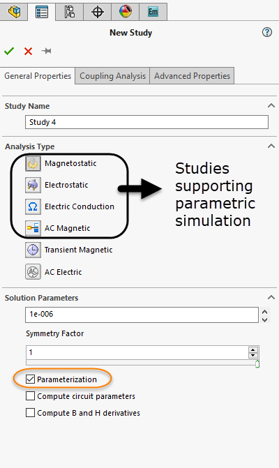
Figure 1- To enable parametrization
Once you have enabled Parametrization in the study, we need to decide the type of parametric simulation we need to perform. We can have SOLIDWORKS geometry dimensions, simulation variables or a combination of both as a parameter. We can also have multiple parameters in the same study to create numerous what-if scenarios.Creating a SOLIDWORKS dimension as a parameter
To include SOLIDWORKS dimensions as a parameter, we need to first open the Parameters dialog box. One can access the same by RMB (Right mouse button) on the assembly name (above all the studies) in the EMS study tree and select Parameters. This is highlighted in Figure 2 below. Now from the screen select the appropriate SOLIDWORKS dimension to create a parameter.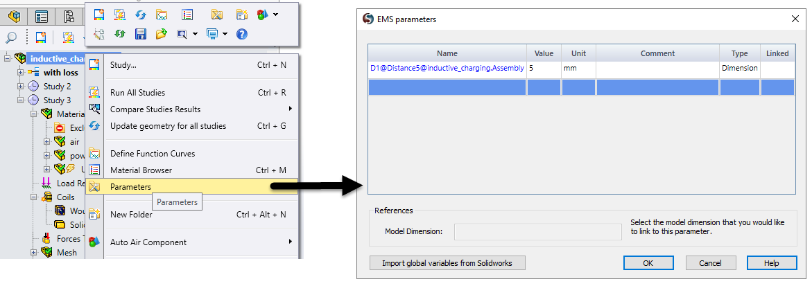
Figure 2- Selecting a SOLIDWORKS dimension as a parameter
Creating a simulation variable as a parameter
Nothing special needs to be done to make the simulation variables as a parameter. Once you have defined the study and created all the components in a study like creating coils, assigning boundary conditions, creating mesh controls etc, you can use any of these as a parameter.Creating Design Scenarios
Once we have created all the parameters and defined the study completely, it is time to create design scenarios where parameters can be used. To create a design scenario just double click on the Design Scenarios under Parameterization folder in the EMS study tree. You can select the parameters you want and then assign possible values for them. Here one can include both geometric variables as well as simulation variables to parameterize. If you already selected a SOLIDWORKS dimension earlier, it will automatically appear under geometric variables. You can refresh scenarios to include all the possible combinations you want to simulate. Refer to Figure 3 below on how to access Design Scenario page in EMS.
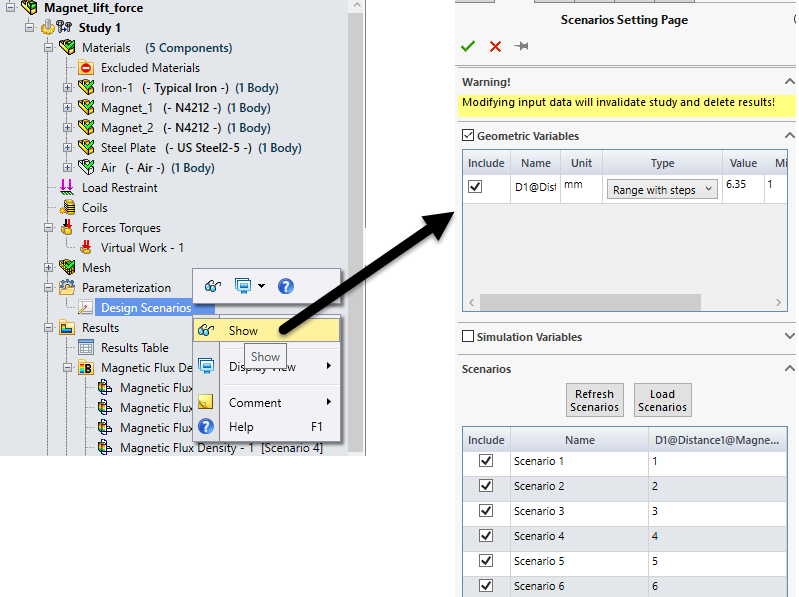
Figure 3- Design Scenarios
Run the Study and look at the Results
Once the design scenarios are setup, you can run the study. Once it is solved, you will be able to access the results for all the scenarios.Examples of Parametric Simulation
Figure 4 shows how the force on a steel plate in a magnet arrangement changes with the distance between the steel plate and the magnet arrangement. EMS automatically plots the Force as a function of distance and all the relevant plots for all the scenarios.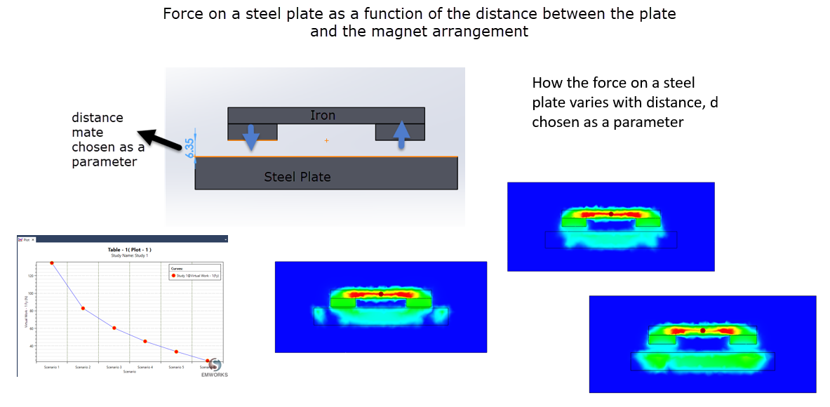
Figure 4- Example 1 - Force variation with distance
Figure 5 shows how parametric simulation can be used to study how the current through the coil influences the force acting on the plunger in a linear actuator.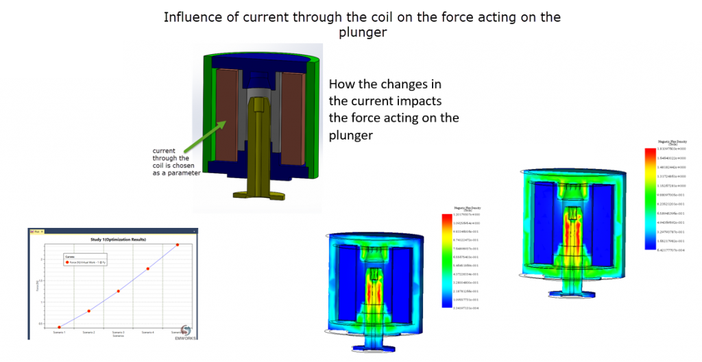
Figure 5- Example 2 - Influence of current on the plunger movement
Figure 6 shows how parametric simulation can be used to study the influence of magnet size in the flux produced at a distance from the Halbach array.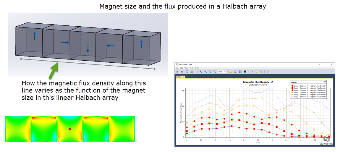
Figure 6- Example 3 - Size of the magnet in a Halbach array is treated as a parameter