

Magnetic Gear
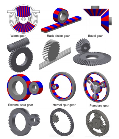
Gears and gearboxes traditionally suffer from issues like friction, heat, and noise, reducing reliability and efficiency. Magnetic gears offer a solution, providing frictionless transmission and overload protection. They are ideal for applications requiring safety and efficiency, including overload protection systems, clean room environments, and powered mobility. Various magnetic gear structures cater to diverse roles and geometries, as depicted in Figure 1.
Despite their benefits, magnetic gears encounter challenges like size and cost. To address these, industry and academia are enhancing their performance. Finite Element Method (FEM) aids in their design and analysis, offering solutions for linear and nonlinear problems. EMWorks2D, a 2D FEM tool, enables accurate magnetic and electric problem-solving, especially beneficial for approximating real-life issues into 2D problems. This article utilizes EMWorks2D to analyze torque and magnetic flux density in two coaxial magnetic gear models, comparing torque results with reference data.
2D simulation of coaxial magnetic gear [2]
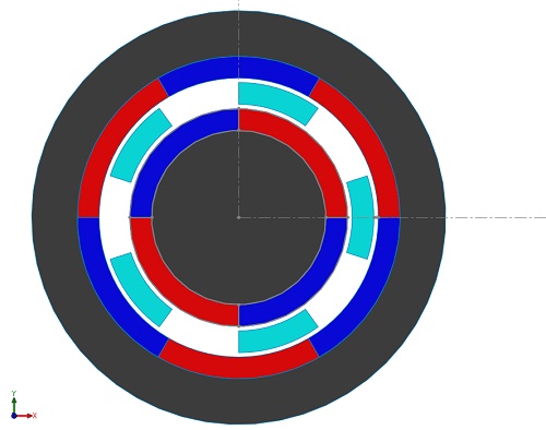
The magnetic gear model, as discussed in [2], comprises a Pi=2 pole-pairs inner rotor and a Po=3 pole-pairs outer rotor with Q=5 ferromagnetic pole-pieces. The inner rotor, operating at a higher speed, is termed the high-speed (HS) rotor, while the outer rotor, with a lower speed but higher torque, is designated as the low-speed (LS) rotor. Using EMWorks2D, magnetic flux, and torque analysis is conducted, neglecting end effects. The iron cores exhibit infinite permeability, while the magnets possess a remanence of 1.2T and $$ \mu_{r} = 1 $$, featuring alternating radial magnetization. Key properties are summarized in Table 1, and Figure 2 illustrates the 2D model.
| Items | Value |
| Radius of the inner rotor yoke | 40.00 mm |
| Outer radius of the inner rotor PMs | 50.00 mm |
| Inner radius of the slots | 52.00 mm |
| Outer radius of the slots | 62.00 degree |
| Slot opening | 36.00 deg |
| Inner radius of the outer rotor PMs | 64.00 mm |
| Inner radius of the outer rotor yoke | 74.00 mm |
| Axial length | 100.00 |
| Pole-pairs inner rotor | 2 |
| Pole-pairs outer rotor | 3 |
| Ferromagnetic pole-pieces | 5 |
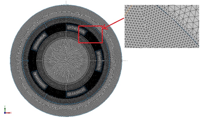
EMWorks2D features an automatic and adaptable mesher that produces triangular mesh elements, ensuring accuracy in simulations. A mesh refinement is specifically applied to the air gap region for precise outcomes. Figure 3 illustrates the mesh plot generated by EMWorks2D, showcasing its capability in meshing the model effectively.
Initially, the LS rotor and the ferromagnetic pieces remain stationary while the HS rotor rotates with an angle φᵢ ranging from 0° to 90°. EMWorks2D conducts a parametric sweep analysis to calculate magnetic flux and torque results concerning the inner rotor angle. Figures 4a) and 4b) depict the magnetic flux density distribution inside the model at φᵢ equals 0° and φᵢ equals 52°, respectively, highlighting high flux spots in the ferromagnetic bodies. Figure 5 illustrates the non-homogeneous distribution of magnetic flux density in the air gap region at φᵢ equals 52° due to the positions of the poles of the inner and outer rotors. Additionally, Figure 6 displays the magnetic vector potential lines, demonstrating how the ferromagnetic pieces facilitate the conduction of magnetic flux in the intermediate air region between the HS and LS rotor poles, resulting in a predominantly circulating magnetic flux density within the magnetic gear device.
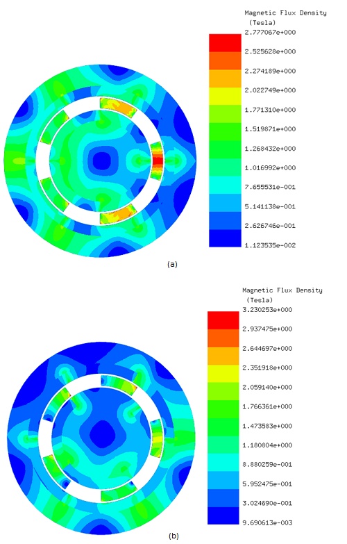
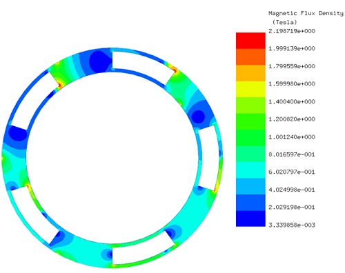
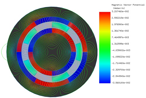
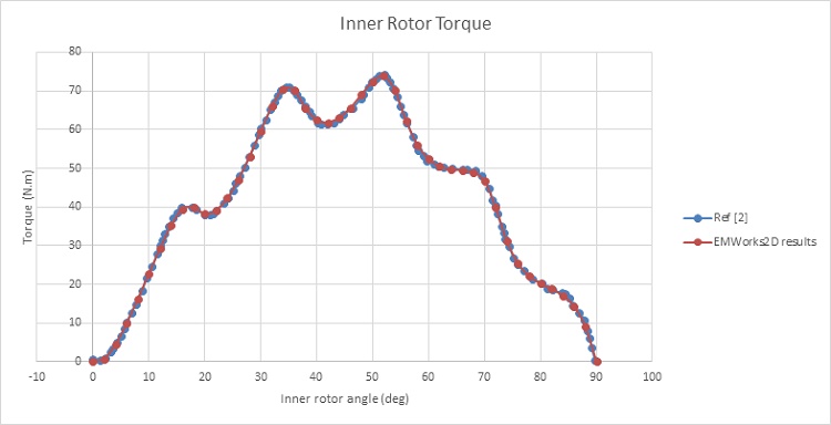
Figure 7 illustrates the magnetic torque generated on the HS rotor while the LS rotor and the ferromagnetic pieces remain stationary. At φᵢ equals 0°, the torque is nearly null, then gradually increases until reaching a first peak of 70 N.m at φᵢ equals 35°. Subsequently, the torque curve reaches a second peak of 74 N.m at φᵢ equals 51°, after which it decreases until becoming null again at φᵢ equals 90°.
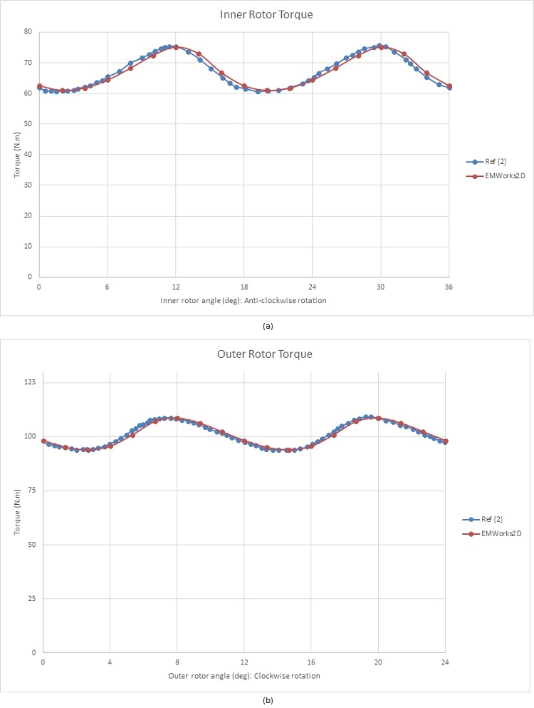
When both the inner and outer rotors rotate in opposite directions, with the ferromagnetic pieces fixed, the outer rotor angle φₒ is defined as: φₒ = -φᵢ * (pᵢ / pₒ) [2]. Starting with the HS rotor positioned at φᵢ = 40 degrees, the torque is approximately 62 N.m, while it reaches about 98 N.m in the LS rotor. Figures 8a) and 8b) depict the resulting torques in the inner and outer rotors, respectively. The average torque generated in the HS rotor is approximately 67 N.m, compared to nearly 101 N.m in the LS rotor, resulting in a gear ratio of approximately 3:2. Consequently, when the inner rotor rotates, the torque is amplified by 1.5 times by this magnetic gear system.
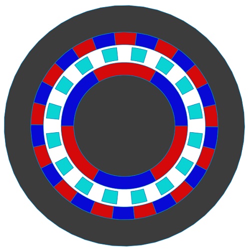
To address the high ripple torque characteristic of the previous model, a new design with increased pole-pairs has been created and analyzed [2]. Illustrated in Figure 9, this updated magnetic gear structure features Pi=3 inner rotor pole-pairs and Po=13 outer rotor pole-pairs, resulting in a gear ratio of 4.33. Additionally, the model incorporates Q=16 ferromagnetic pieces.
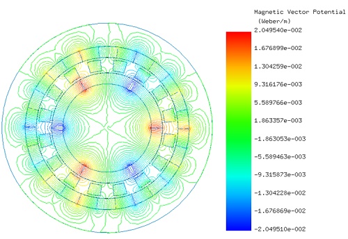
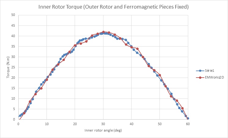
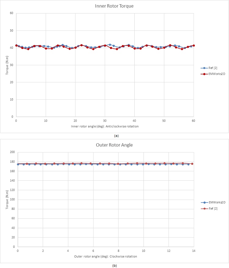
In Figure 10, the flux lines are depicted, showcasing the transmission of flux through the air gap facilitated by the intermediate ferromagnetic pieces. Following a similar methodology as before, torque analysis is conducted with the HS rotor rotating while the LS rotor and ferromagnetic pieces remain fixed ( $$ \phi_{i} $$ varies from 0° to 60°). The resulting torque curve of the HS rotor is displayed in Figure 11, peaking at approximately 41 N.m when $$ \phi_{i} = 30^{\circ} $$. Figures 12a) and 12b) illustrate the torque curves of the inner and outer rotors respectively, when they rotate in opposite directions. The HS rotor generates a torque of 41 N.m, while the LS rotor produces about 175 N.m. These torque values align with the calculated gear ratio and exhibit reduced ripple effects, particularly evident in Figure 12b), where ripples are nearly eliminated.
Magnetic gears offer a revolutionary alternative to traditional systems, showcasing superior efficiency and reliability. Through advanced analysis and simulation, this study illuminates the immense potential of magnetic gears. Utilizing tools like EMWorks2D and Finite Element Method (FEM) analysis, we propel innovation in magnetic gear design, promising a future of enhanced power transmission solutions. With ongoing research and development, magnetic gears are poised to redefine industries, ushering in a new era of sustainable and reliable technology.
References
[1]:P.M. Tlali, R-J. Wang, S. Gerber. Magnetic Gear Technologies: A Review. IEEE: 2014 International Conference on Electrical Machines (ICEM)
[2]:Thierry Lubin, Smail Mezani, Abderrezak Rezzoug. Analytical Computation of the Magnetic Field Distribution in a Magnetic Gear.