

Introduction
EMS for SOLIDWORKS can be coupled with SOLIDWORKS Motion to perform combined Electro-Magnetic and Motion simulation. This type of simulation is very powerful and can simulate many real-life problems such as Linear actuators, Rotary actuators, Magnetic levitation devices, Eddy current breaking, Voice coils, Magnetic clutches and NDT sensors. The following EMS studies can be coupled to Motion – Magnetostatic, Transient Magnetic and Electrostatic.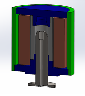
Figure 1 - Section view of a linear actuator to be simulated using coupled Motion and EM simulation.
Important items to keep in mind while creating the model
Assembly mates
1. The mates must be properly defined so that SOLIDWORKS Motion can correctly capture the movement of the moving parts. In the example shown in Figure 1 the movable plunger can move inside its slot but is always concentric to the inner circular slot. Further it is not free to turn while it moves. Hence, a concentric mate which locks the Rotation must be employed as shown in Figure 1.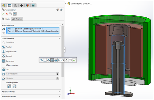
Figure 2 - Use of concentric mate with Lock Rotation.
2. Further, we restrict the motion of the plunger using a Limit mate as shown in Figure 3. The use of limit mate allows the maximum distance between the top of the plunger and the fixed face to be 6 mm and the minimum distance to be 2 mm. This will ensure that the plunger stops when it is at 2 mm from the top.
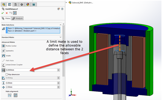
Figure 3 - use of Limit Mate.
3. All non- moving parts (including the band and Air, which are discussed below) are set to Fixed as shown in the study tree in Figure 4.
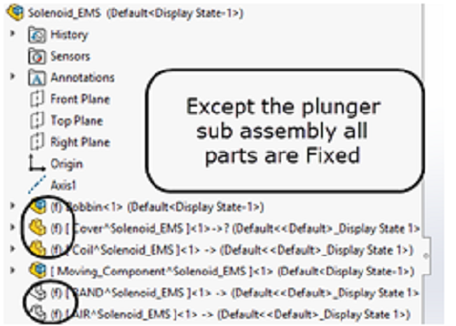
Figure 4 - All non-moving parts are set to Fixed.
4. If there are more than one moving part, then it is better to club all the moving parts inside a sub assembly as shown in Figure 5. In this example, the Moving_Component subassembly contains 2 parts –Armature and air (shown in blue). Typically, it is recommended to make any air cavity in the moving part as a part of the moving sub assembly.
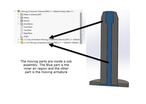
Figure 5 - All moving parts are inside a sub-assembly.
5. Ensure that you can manually move the subassembly in SOLIDWORKS and the motion behaves as expected.
6. All moving parts must be assigned a material in SOLIDWORKS . This ensure that SOLIDWORKS Motion uses the correct material properties to compute the dynamic response of the moving parts. In this example since the moving sub assembly contains 2 parts we assign the following materials – Armature – Steel 1010, Air – Air. You need to reassign these materials in the EMS interface also.
Creation of BAND
Band is a SOLIDWORKS part which encloses all the moving parts. Creating a band is obligatory for doing a coupled EM- Motion simulation. In this example, the band should completely enclose the subassembly that can move. We need a band geometry because EMS only meshes the components inside the band at every time step. This reduces the meshing time in each time step thereby reducing the time for an overall solution. One must adhere to the following rules while creating a band geometry.- A band must completely enclose all moving parts. At all time, the moving parts cannot leave the band.
- A band can touch other non-moving parts in the assembly.
- The band is typically assigned a material of Air since it is a fictitious part created to enable coupled EM-Motion simulation.
- In the assembly, the band part must be fixed and it is often convenient to assign transparency to this part to better view the moving subassembly inside it.
- There must be only one band in the entire assembly.
- All the moving parts inside the band must be subtracted from the band geometry using the Cavity feature in SOLIDWORKS .
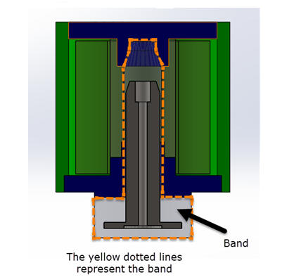
Figure 6 - The band geometry
Air geometry
To do an EM simulation, we need an Air geometry. When the Air geometry is created one must ensure that all the components including the band must be subtracted from the Air by using the Cavity feature in SOLIDWORKS Typically, this air geometry will be the final part created in the assembly. Also make sure that the Air geometry if fixed. Once it is created, use the Interference Detection feature in SOLIDWORKS to ensure that there is no interference in the assembly as shown in Figure 7.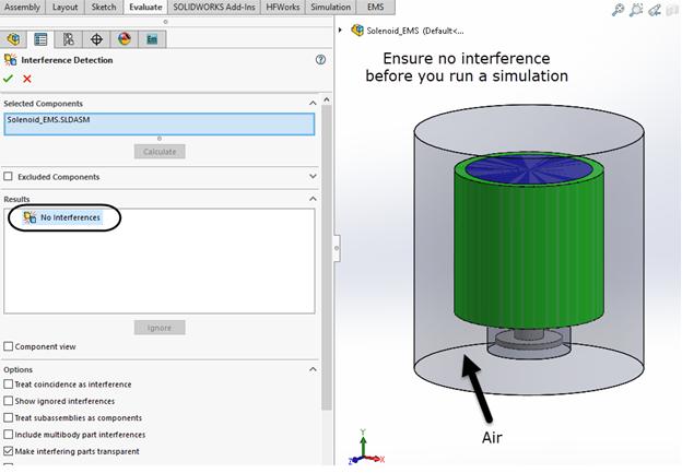
Figure 7 - Interference detection.
If you find interference in your assembly, check the following – a)Make sure that from the Band part all the moving parts are subtracted using the cavity option. b)Make sure that from the Air geometry all parts including the band part are subtracted using the cavity option. c)Ensure that other parts in your assembly (other than the Band and Air) do not have any interference. d)Remember, to do a EMS simulation there must be no interference in the assembly.Simulation and Results
The solenoid coil was excited using DC current and the force acting on the moving armature is used in the SOLIDWORKS Motion simulation to move the armature. This article does not talk about the setup involved in EMS. Figure 8 shows the section plot of the Magnetic Flux Density as well as the response characteristic of the plunger (both displacement of the center of mass and velocity as a function of time).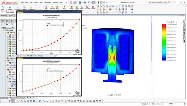
Figure 8 - Magnetic flux density and dynamic response