

Introduction
Crossovers play a crucial role in monolithic Integrated Circuits (IC) and antenna arrays, facilitating two signal paths to cross with high isolation and matched ports. Various crossovers, including air bridges, bond wires, and printed planar types for single and dual bands, enable signal connections and transport between layers. Coupled transmission lines are often employed in the design of power dividers, couplers, and filters, with recent applications extending to the creation of band-pass filters using lines loaded with open/shorted stubs. This article discusses the design of a compact single planar crossover based on coupled lines, with an analysis of its electromagnetic behavior through S Parameters using a full wave 3D simulator.
The Model Geometry
This compact planar crossover, incorporating two coupled lines with two open stubs, is tuned to a resonance frequency of 1.8GHz. It is built on a dielectric substrate characterized by a relative permittivity of 2.65 and a dielectric loss tangent of 0.003. The crossover's dimensions are approximately 48 mm x 30 mm x 0.508 mm, providing a concise and efficient design. A 3D model of this configuration is depicted in Figure 1, showcasing its compact structure and engineering precision.
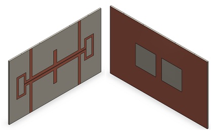
Figure1 - The 3D CAD Model of the compact planar crossover (front and end view)
In this configuration, two transmission lines are interconnected at ports 1 and 4, as well as ports 2 and 3, as illustrated in Figure 2. To enhance the impedance ratio between even and odd mode impedances of the coupled lines, the ground plane is strategically slotted using a patterned ground-plane technique. The key parameters of the structure are concisely summarized in Table 1, providing a clear overview of its design specifications.
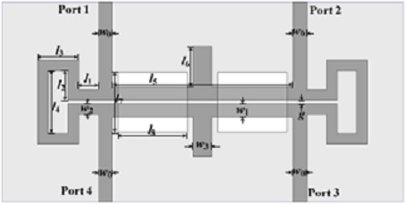
| Parameter | Value (mm) |
| l1 | 2 |
| h2 | 4 |
| l3 | 5.05 |
| l4 | 8.2 |
| w0 | 1.4 |
| w1 | 1.35 |
| w2 | 1.05 |
| w3 | 1.81 |
| g | 0.2 |
Simulation Results
The simulated S parameters (S11 and S31) obtained through HFWorks, alongside the measured results for the single band crossover, are displayed in Figure 4. These parameters are presented across a frequency range from 0.5 GHz to 3.5 GHz, with the central frequency centered around 1.8 GHz. This visualization aids in understanding the crossover's performance over a broad frequency spectrum, highlighting its effectiveness at the targeted resonance frequency.
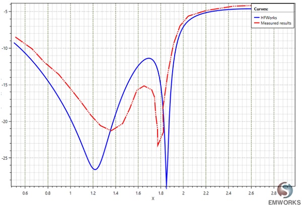
Figure 3 - The return loss S11 measured and simulated results
The transmission coefficient |S31| is greater than -0.6 dB while the simulated |S11| is less than -20 dB for 1.81 - 1.875 GHz.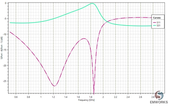
Figure 4 - S11 and S31 of the single band crossover
The isolation|S21| and |S41| are less than -20 dB for 1.73 - 1.814 GHz, and 1.81 – 1.87 GHz respectively, as shown in Figure 5.
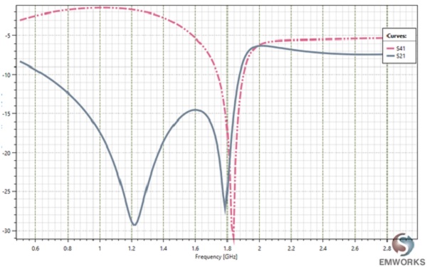 Figure 5 - S41 and S21 of the single band crossover
HFWorks automatically computes the electromagnetic field. The distribution of the electric field at the resonance frequency is shown in Figure 6. The incident power is 1W.
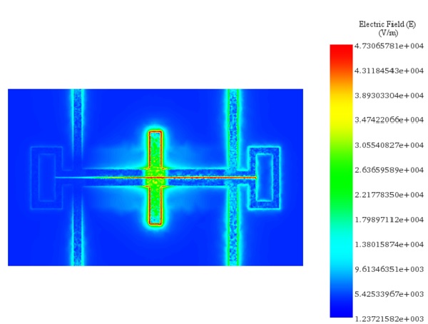
Figure 6 - Distribution of the electric field at 1.80 GHz
This blog delves into the intricacies of enhancing signal isolation and transmission in integrated circuits (ICs) and antenna arrays using compact single-band planar crossovers. Through detailed design and HFWorks simulation, it showcases the effectiveness of these crossovers at a resonance frequency of 1.8GHz, providing high isolation and matched ports with minimal loss. The article highlights the importance of precise geometry and material selection, offering a valuable resource for engineers looking to optimize electronic systems for compactness and efficiency. This exploration not only advances the field of electronic design but also guides practical implementations in modern electronic devices.
References
[1] https://www.emworks.com/product/ATLASS [2]Wenjie Feng, Tianyu Zhang, WenquanChe“Compact Single-band Planar Crossover Based on Coupled Lines”Proceedings of the 46th European Microwave Conference, pp. 975 – 978, Oct 2016.