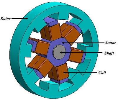
A Switched Reluctance Motor
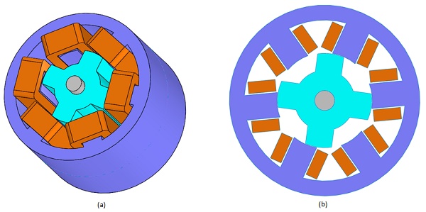
SRMs employ salient poles in both the stator and rotor (Figure 1). Stator coils are wound around poles, while the rotor minimizes eddy current losses. Motor rotation relies on sequenced current pulses, timed precisely to the rotor position.
FEM and CAD modeling streamline SRM development, saving time and resources. Using MotorWizard, CAD geometry integrates with numerical simulation for efficient analysis. 2D FEM approximation enables rapid assessment of magnetic flux density and static torque against rotor angle, aiding in peak identification. Comparison with published data validates static torque results.
EMWorks 's electric Motors design and simulation package
EMWorks offers MotorWizard: a powerful package to create and simulate electrical motors.
Geometry generation
Step 1: Build the SRM
The initial phase of SRM analysis involves creating a 2D model. Key motor properties are detailed in Table 1 (ref [1]). After selecting the stator position (inner or outer), specific parameters are determined:
1. General sizing settings: Specifies rotor and stator pole numbers, and phase numbers, ensuring even pole numbers compliant with the phase number.
2. Stator properties: Defines outer and inner stator diameter, yoke thickness, stator arc angle, and length for 3D models. Winding geometrical properties are also inputted here.
3. Rotor properties: Outlines outer and inner rotor diameter, yoke thickness, stator arc angle, and length for 3D models.
4. Model validation and generation: Allows users to ensure model consistency before creation.
| Stator poles number | 6 |
| Rotor poles number | 4 |
| Stator outer core diameter | 76 mm |
| Rotor outer core diameter | 37.55 mm |
| Air gap length | 0.2375 mm |
| Stator pole width | 9.915 mm |
| Stator pole width | 10.5 mm |
| Motor length | 50 mm |
| Shaft diameter | 8 mm |
Figure 2 shows both 3D and 2D models. The 2D model will be used to perform the FEM simulation.
Step 2: 2D FEM simulation
2D simulation of the SRM is performed next using MotorWizard.
In this analysis, two windings, aligned with the rotor pole and belonging to the same phase, are defined. Each winding phase comprises 20 turns carrying a 4A DC current. The rotor and stator are constructed from non-oriented silicon steel M 27. Figure 3 illustrates the BH curve of M 27.
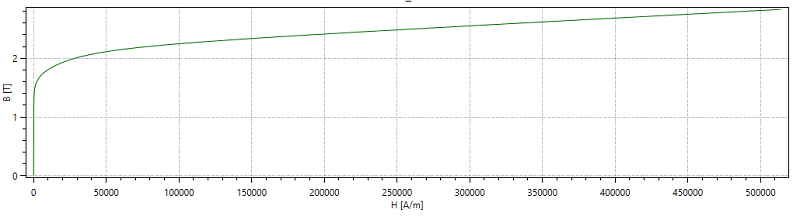
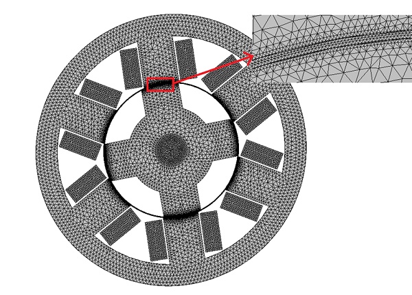
Figure 4 displays the generated mesh within the 2D model, with the capability to apply mesh refinement control on edges and surfaces. In this instance, a mesh control featuring smaller element sizes is employed specifically on the air gap between the aligned poles. The air gap is represented as a thin ring between the rotor and the stator.
The Magnetostatic module of MotorWizard computes and generates various results including magnetic flux density, magnetic field intensity, applied current density, Back EMF, inductance matrix, DC resistance, flux linkage, etc. Diverse shapes and types of plots are created to visualize these results. Additionally, to evaluate static torque results against rotor angle, a parametric analysis is defined.
Results
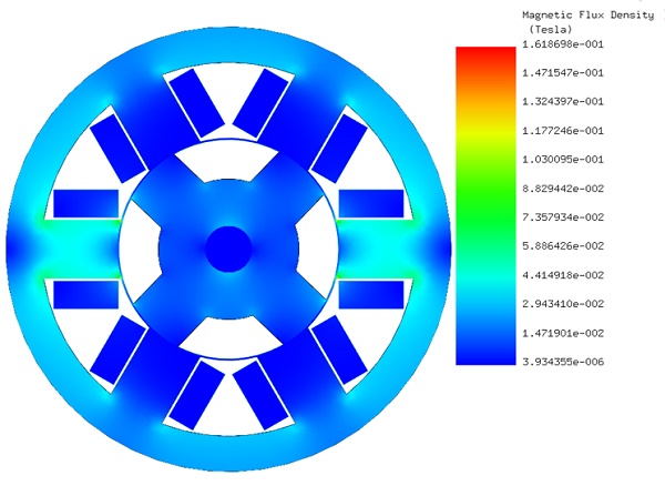
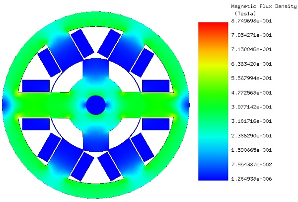
Figure 5 presents the magnetic flux density plot at the unaligned position (zero degrees), where the rotor pole opposes the stator slot, leading to maximum motor reluctance. Notably, the peak magnetic flux density is approximately 0.16 T.
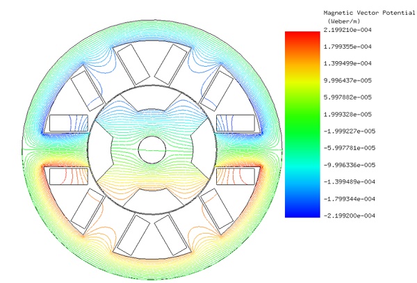
In Figure 6, equipotential contours of magnetic potential A, representing magnetic flux lines with perpendicular current flow, reveal a discontinuity due to the high magnetic reluctance caused by the large air gap.
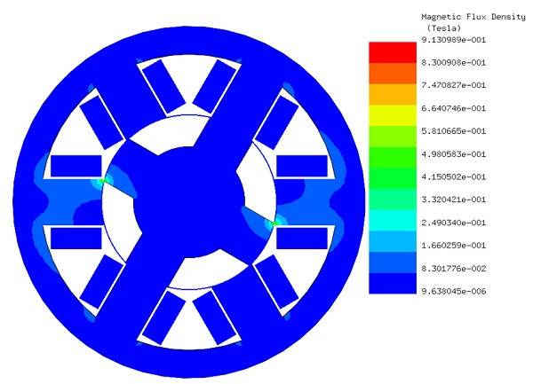
Transitioning to the aligned position (45 degrees) depicted in Figure 7, where the rotor pole fully aligns opposite the stator pole, minimizing magnetic reluctance. Here, the peak magnetic flux density reaches around 0.87 T.
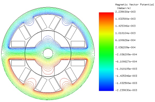
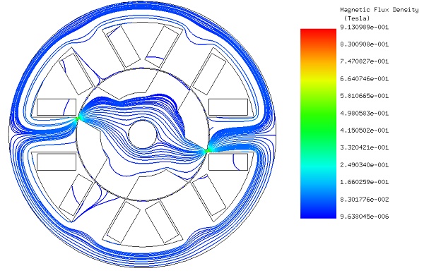
Figure 8 illustrates the flux lines, smoothly traversing the ferromagnetic path from stator to rotor components without discontinuity, attributed to the small air gap.
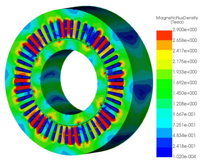
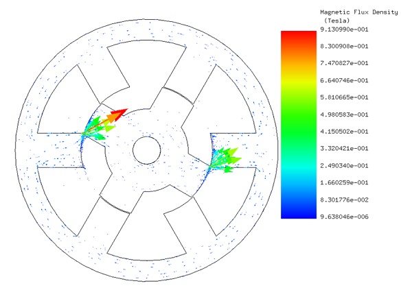
Figures 9 (a), 9 (b), and 9 (c) display the magnetic flux density, fringe plot, vector plot, and lines plot, respectively, at the rotor position of 16 degrees. At this precise position, both magnetic flux and torque reach their maximum values, measuring 0.913 T and 0.0304 Nm, respectively.
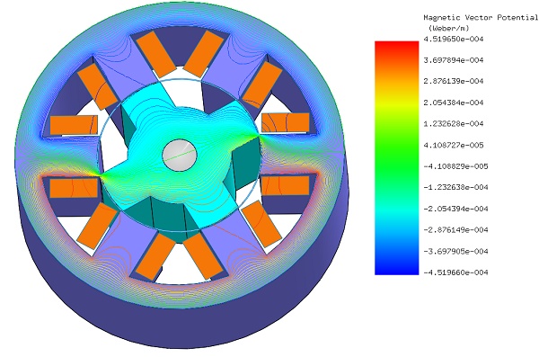
In Figure 10, the equipotential contours of A plot are superimposed on a cross-section view of the motor's 3D model, providing further insight into the magnetic field distribution.
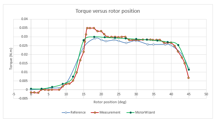
Figure 11 elaborates on a torque comparison, indicating measurement data from ref [1] showing a maximum value of 0.0349 Nm at 16 degrees. Comparatively, the torque computed by MotorWizard, along with the values provided in ref [1], peaks at 0.03 Nm and 0.029 Nm, respectively. This slight discrepancy can be attributed to the neglected end effect in the 2D simulation.
Conclusion
The application note explores the optimization of a Switched Reluctance Motor (SRM) using EMWorks's MotorWizard for 2D Finite Element Method (FEM) simulation, highlighting its benefits in motor design and analysis. It details the process from geometry creation, through 2D FEM simulation, to analyzing magnetic flux density, torque, and other key performance metrics against rotor angle, comparing results with published data for validation. The study reveals significant insights into the magnetic behavior of SRMs, including the variation of magnetic flux density and torque with rotor position, demonstrating maximum efficiency when rotor poles align with stator poles, and minimizing magnetic reluctance. The findings, showcasing a peak magnetic flux density of 0.87 T at an aligned position and a maximum torque of 0.0304 Nm at 16 degrees rotor position, validate the simulation's accuracy. It concludes that EMWorks's MotorWizard is an effective tool for SRM design, offering a streamlined approach for simulating and optimizing motor performance, thereby saving time and resources in the development phase.
References
[1]: Torsten Wichert, M.Sc. Design and Construction Modifications of Switched Reluctance Machines. Warsaw university of technology, Institute of Electrical Machines
[2]: Kazuhiro Ohyama, Maged Naguib F. Nashed, Kenichi Aso, Hiroaki Fujii, and Hitoshi Uehara.Design Using Finite Element Analysis of Switched Reluctance Motor for Electric Vehicle. Department of Electrical Eng., Fukuoka Institute of Technology, Fukuoka, Japan,Electronics Research Institute, Cairo, Egypt and Meiwa Manufacturing Co., Ltd, Fukuoka, Japan. 0-7803-9521-2/06/$20.00 §2006 IEEE.