

Inductive Power Transfer
Inductive Power Transfer (IPT) technology facilitates wireless energy transmission through air gaps via coupled inductors, prominently used for electric vehicle (EV) contactless charging. An IPT system typically includes a primary power supply, a secondary pick-up controller, and a coupled magnetic structure. This case study focuses on designing circular charging pads, using the EMS package for simulating pad inductance.
Charging Pads Model
Objective
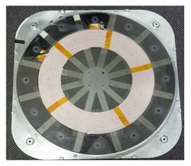
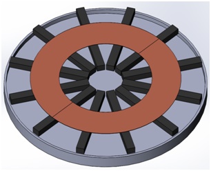
The IPT system features two circular pads as controllers, each equipped with a Litz wire coil and 12 ferrite strips (illustrated in Figure 1. a and 1. b). The air gap between these pads directly influences the magnetic flux generated by the AC current through the primary pad. This study aims to calculate the primary pad's inductance relative to the air gap size to optimize magnetic flux at a steady AC frequency.
(a) (b)
(c)
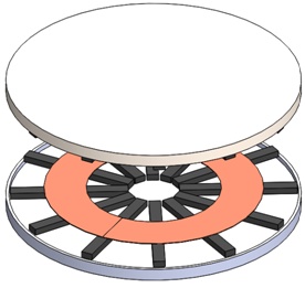
Figure 1. IPT charging pads: (a) real-world system [1, p. 76], (b) 3D model of the primary circular charging pad (c) 3D model of the full IPT circular charging system
Circular Pads Model
The circular pads, as depicted in Figure 1. b, consists of three main components: a Litz wire coil placed over 12 radial ferrite strips, evenly spaced, and affixed to a backing plate. Each component is crafted from distinct materials, with Table 1 providing a summary of the materials selected for designing these building blocks.
Table 1. The list of materials used for the design of the circular charging pads.
| Component | Material |
| Backing Plate | Aluminum |
| Litz wire coil | Copper |
| Ferrite strips | Ferrite isotropic material with a relative permeability of 2000 |
Furthermore, the Litz wire coils in the circular charging pads each comprise a 12-turn wound current coil. The transmitter coil carries a current of 30 Amps (RMS), whereas the receiver coil remains open-circuited, with no current flow (0 Amps RMS).
IPT Charging System Analysis
Study parametrization
Leveraging the EMWorks EMS package, a parametric AC magnetic study was conducted to investigate the electromagnetic properties of the circular pads. According to Table 2, the simulation was performed at a frequency of 20 kHz, with the vertical airgap distance adjusted between 90 mm and 250 mm. The inductance of the primary pad was assessed while the secondary pad was open-circuited.
Table 2. Study configuration.
| Study Type | Parametric AC Magnetic |
| Frequency (kHz) | 20 kHz |
| Airgap offset (mm) | 90- 250 mm |
Analysis Results
Following the meshing process (illustrated in Figure 2) and conducting the parametric AC magnetic study, the outcomes were documented, as shown in Figure 3.
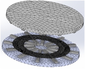
Figure 2. IPT circular charging system meshed.
Based on the study parameters outlined in Table 2, the inductance of the primary circular charging pad changes from 148 mH with a vertical airgap of 90 mm to 132 mH at a 250 mm offset. This change in primary pad inductance is detailed in Figure 3, alongside simulation results referenced from [1, p. 77].
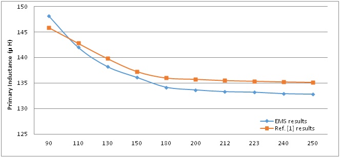
Figure 3. The evolution of the primary pad inductance in the function of the airgap offset compared to reference [1, p. 77].
Conclusion
Inductive Power Transfer (IPT) technology enables wireless energy transmission through air gaps, commonly used for contactless charging in electric vehicles (EVs). This case study delves into designing circular charging pads and simulating pad inductance using the EMS package. The IPT system comprises primary power supplies, secondary pick-up controllers, and coupled magnetic structures. Circular pads equipped with Litz wire coils and ferrite strips are analyzed to optimize magnetic flux at a steady AC frequency relative to air gap size. Leveraging the EMWorks EMS package, a parametric AC magnetic study explores electromagnetic properties at varying air gap distances. Results demonstrate changes in primary pad inductance with air gap offset, crucial for IPT charging system optimization. This study provides valuable insights for enhancing wireless charging efficiency in EV applications.
References
[1] Chang-Yu (David) Huang, “Design of IPT EV Battery Charging Systems for Variable Coupling Applications,” PhD Thesis in Electrical and Computer Engineering, the University of Auckland, 2011.

