

電磁界–回路 連成シミュレーション
高精度な過渡解析および AC 解析のための双方向連成
EMWORKS における回路連成
回路連成は、3D 電磁界モデルを電気回路図と統合し、精密なシステムレベルシミュレーションを可能にします。
連成シミュレーションの仕組み
解析中、2つのソルバーが連続的に相互作用します:
電磁界ソルバー: 3D ジオメトリ内の磁束結合、誘導電圧、電流分布、損失を計算。
回路ソルバー: これらの電磁界量を回路図内のポート量として利用。回路の電流・電圧は次の電磁界計算の境界条件となります。
このやり取りにより 双方向の連成 が生まれ、飽和、逆起電力(Back-EMF)、非線形インダクタンスなどの実際の現象を正確に再現します。
シミュレーションワークフロー
3D EM モデルを定義: 材料、コイル/導体領域、ソース、境界条件をジオメトリに割り当て。
回路ポートを割り当て: 3D ジオメトリ内のコイルや導体経路を電気端子として定義。端子は回路モデルと電圧・電流を交換。
外部回路を作成: ソース、負荷、受動素子、スイッチング素子、制御素子を用いて回路図を作成。EM ポートを回路内の適切なノードに接続。
連成問題を解く:
時間領域: 各時間ステップで EM ソルバーと回路ソルバーが値を交換(過渡解析)。
周波数領域: AC 解析のために EM ソルバーがインピーダンスやポートパラメータを提供。
結果の後処理: 回路データとフィールドデータを同時に確認。
主な機能
双方向フィールド–回路連成: 回路条件が EM モデルを駆動し、誘導電圧などの EM 量が回路にフィードバックされます。
解析サポート: モータ、コンバータ、スイッチングシステムの過渡解析(時間領域)およびインピーダンス・共振研究の定常 AC 解析(周波数領域)をサポート。
巻線・ポート表現: 3D モデル内のコイル、導体、端子は定義された電流・電圧を持つ電気ポートとして表現。
マルチフィジックス統合: 回路連成は、運動、熱、構造解析などの他の解析と組み合わせて、完全に連動した物理挙動を評価可能。
典型的な応用
回路連成は、電磁デバイスの性能が接続された電気システムに直接依存する場合に必要です:
変圧器およびインダクタ: 整流器やスイッチング回路接続時の励磁電流、漏れインダクタンス、鉄損の解析。
モータおよび発電機: インバータやドライブ、制御器接続時のバック EMF、トルク、過渡立ち上がりの評価。
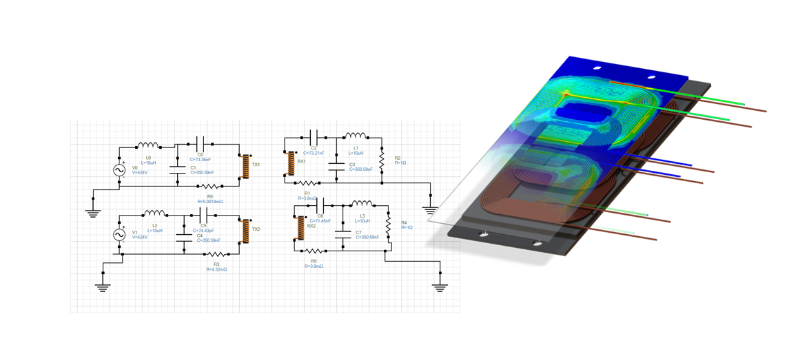
ワイヤレス電力システム: 送受信コイルに接続された共振タンク回路や補償ネットワークのシミュレーションで効率と感度を評価。
誘導型センサおよび検出コイル: 電磁界に基づき、ピックアップコイルや検出素子の出力電圧・電流を計算。
結果と出力データ
連成シミュレーションでは、回路と電磁界の結果を完全に取得可能です:
回路量: 電圧、電流、電力フロー、損失、効率(時間または周波数依存)。
フィールド量: 電磁界モデルの電界、損失(渦電流、ヒステリシス、銅損)、磁束。