

Renewable energy, also referred to as green or clean energy, originates from natural processes that replenish over short timeframes and are not exhaustible. Biomass, geothermal, hydropower, solar, and wind are among the most prevalent renewable energy resources. Notably, the generation of clean energy doesn't accrue environmental debt. Moreover, the technologies employed in its production are less polluting or entirely pollution-free, while also sparing resources that aren't readily renewable.
Design and simulation of PM axial flux generator for wind turbine using EMS
Permanent magnet (PM) machines have increasingly supplanted other types of electrical machines across various applications and industries. This shift is fueled by several advantages, including high energy density, robustness of PM materials, excellent corrosion resistance, and reduced demagnetization effects. New PM materials exhibit enhanced tolerance to temperature fluctuations. The design and development of wind generators prioritize attributes such as simple construction, lightweight, high output power, variable-speed generation, and cost-effectiveness. Contemporary power electronics offer improved efficiency, reduced losses, simplified control, and lower costs, enabling adjustments to output voltage and frequency to align with system requirements. Various PM machines, including PM synchronous machines and PM axial flux generators, are employed to harness wind energy.
In this study, we analyze a 3-phase PM axial flux machine. These machines, whether cored or coreless, are favored for their high efficiency, economic viability, compact size, and lightweight construction. Research [2] indicates the superior performance of axial flux machines over radial flux counterparts, with axial flux generators being notably cost-effective. Additionally, axial flux permanent magnet generators with coreless stators boast high power density, making them ideal for energy generation systems [3].
The proposed model, depicted in Figure 3, features a stator comprising 9 stranded coils arranged into 3 winding phases. Each phase consists of 3 series-connected coils with a total of 90 turns. Positioned in the mid-plane of the machine between the upper and lower sides of the rotor, the stator interfaces with two sides of the rotor, each comprising 12 permanent magnets and a laminated steel core. Table 1 details the properties of the Neodymium magnet 4212 utilized for the permanent magnets, while Figure 4 illustrates the BH curve of M-19, employed for the rotor cores.
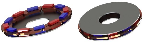
Figure 3 - 3D model of the simulated axial flux generator.
Table 1 - PM material properties
| Relative permeability | Remanence (Tesla) | Coercivity (A/m) | |
| N4212 | 1.205 | 1.35 | 891268 |
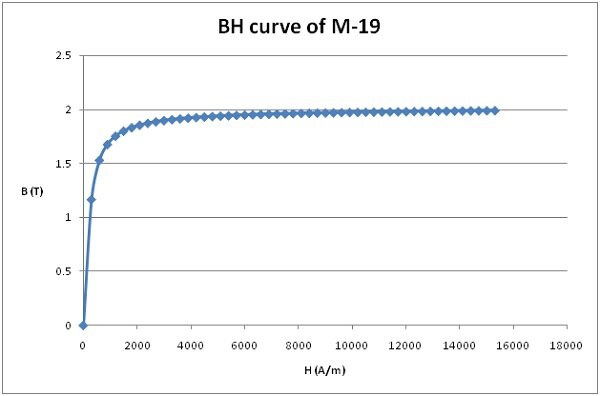
Figure 4 - BH curve of M-19.
Motion Coupling
EMS, as a CAD-Embedded plug-in, integrates electromagnetic fields with motion analysis. This coupling combines both mechanical and magnetic loads. For generators, the EMS Transient module coupled with CAD-Embedded motion analysis computes induced voltages for each phase. The rotor rotates at 1000rpm, and simulations run for 0.01s. Figure 5 illustrates insights from the motion study.
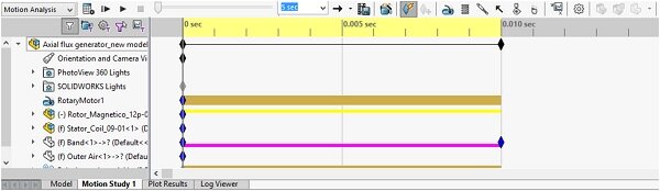
Figure 5 - motion study.
EMS utilizes tetrahedral elements to mesh the simulated geometry. The total number of elements varies depending on the dimensions and shape of the model. EMS offers control over mesh size on specific bodies or surfaces to improve result accuracy in these areas. Below is the meshed model.
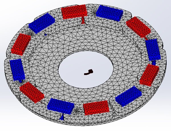
Figure 6 - Meshed model
Results
The EMS Transient module computes instantaneous magnetic quantities such as magnetic flux, force, torque, eddy currents, losses, induced voltages, inductance, and resistance matrices. Figures 7 and 8 depict the magnetic flux density through fringe and vector plots across the entire model and within the magnets at 5.5ms, illustrating the magnetization direction of the PM, which is axially magnetized. Figure 9 displays the magnetic field plot at 10ms. Additionally, Figures 10 and 11 show the rotor's angular displacement and velocity, respectively, with a constant speed of 1000 rpm.
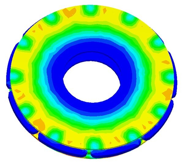
Figure 7 - Fringe plot of the magnetic flux density at 55ms
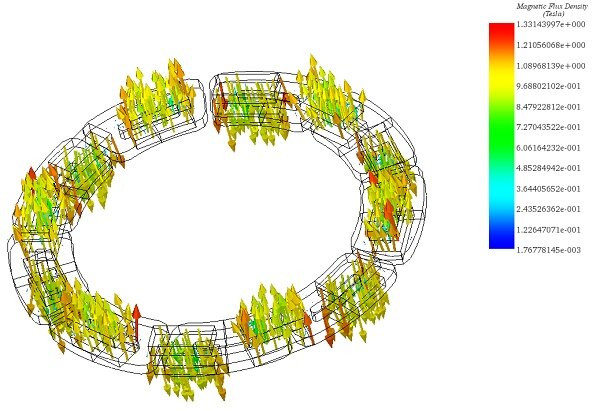
Figure 8 - Vector plot of the magnetic flux density at 55ms
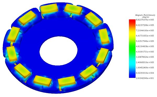
Figure 9 - Magnetic field intensity plot at 10ms
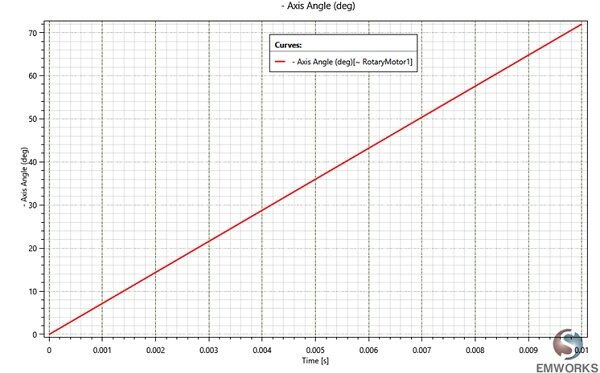
Figure 10 - Angular displacement
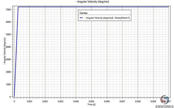
Figure 11 - Angular displacement
Figure 12 illustrates the induced voltage at each phase over time, exhibiting a sinusoidal waveform with a maximum value of 37V. The signal frequency, derived from the time period of one phase, equates to 120Hz, computed from a time period of 0.008333s. Concurrently, Figure 13 displays the flux linkage results relative to the rotor angle, mirroring the characteristics of the induced voltages. Each phase's resistance remains constant over time at 0.45 Ohm, as the coils are stranded (neglecting eddy currents), and the steel used has no electrical conductivity. Additionally, the static inductance measures 0.146 H, with dynamic inductance plotted in Figure 14.
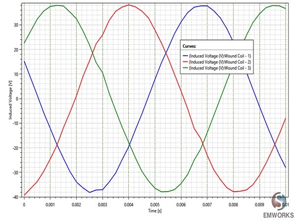
Figure 12 - Induced voltages
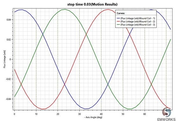
Figure 13 - Flux linkage versus rotor angle
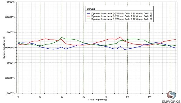
Figure 13 - Flux linkage versus rotor angle
Figure 14 - Dynamic inductances
Figure 15 shows an animation of the magnetic flux density versus time.
Figure 15 - Animation of the magnetic flux density versus time
In conclusion, this comprehensive guide provides invaluable insights into designing and simulating PM axial flux generators for wind turbines. By leveraging cutting-edge tools like EMS, coupled with CAD-Embedded motion analysis, engineers can optimize generator performance with ease. With the rising demand for clean energy solutions, the rapid development of wind power technologies underscores the significance of efficient and cost-effective generator designs. This resource equips professionals with the knowledge needed to meet the evolving demands of the renewable energy industry.
References
[1]: https://www.eia.gov/energyexplained/?page=renewable_home
[2]: Pop AA, Jurca F, Oprea C, Chirca M, Breban S, Radulescu, MM. Axial-flux vs. radial-flux permanent-magnet synchronous generators for micro-wind turbine application. In: 15th European conference power electronics and applications; 2014; p. 1–10.
[3]: Caricchi, F. Crescimbini, O. Honorati, G. Lo Bianco, E. Santini.Performance of coreless- winding axial-flux permanent-magnet generator with power output at 400 Hz, 3000 r/min. IEEE Trans Ind Appl, 34 (1988), pp. 1263-1269