

Wearable technology, a prime example of IoT applications, encompasses smart electronics like smart watches. These devices commonly utilize Bluetooth for connectivity. This article explores the design of Bluetooth antennas for smart watches, focusing on two configurations: flat and bent. HFWorks' Antenna analysis simulates the electromagnetic behavior of these antennas, offering insights into their performance differences.
Flat Bluetooth antenna
Design and simulation
Figure 1 depicts the configuration of the flat Bluetooth antenna structure, operating at 2.45 GHz. The antenna's overall size is specified, and it is excited using a microstrip line with a 50 Ohm impedance. The materials used include FR4 with a relative permittivity of 4.5, while the metals are treated as perfect electric conductors (PEC).

Results
The simulated return loss S11, obtained using HFWorks with the Fast Sweep Type, is illustrated in Figure 2. The frequency range spans from 2 GHz to 3 GHz, showcasing resonance at 2.45 GHz.
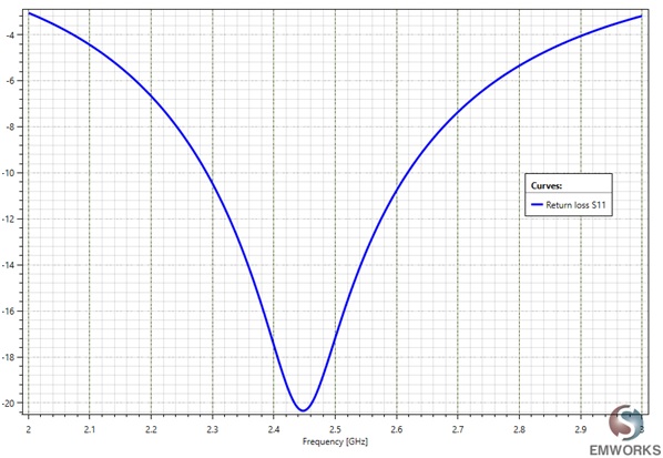
Figure 2 - Return loss S11 of the flat antenna (dB).
The Voltage Standing Wave Ratio (VSWR) is depicted in Figure3. At 2.45 GHz the VSWR is less than 1.2
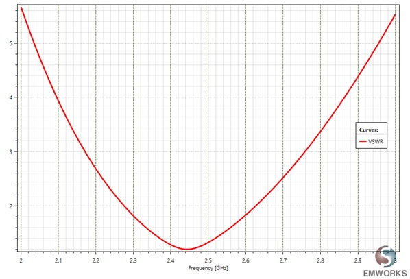 Figure 3 - 2D plot of the VSWR.
Figure 4 presents polar plot views of the far field data, depicting the gain at 2.45 GHz in the XZ, XY, and YZ planes.
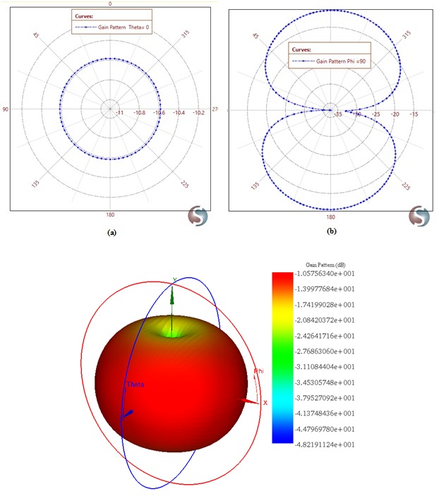
Figure 4 - 2D plot of the gain at 2.45 GHz in the XY, YZ and XZ planes.
Bent Bluetooth antenna
Design and simulation
Studying antenna performance under various bending conditions is crucial for wearable electronics. Different configurations using SOLIDWORKS are presented by varying the bending angle. Figure 5 illustrates the geometry of the bent Bluetooth antenna.
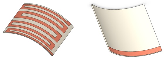 Figure 5 - The geometry of the bent antenna (top and bottom views).
Different bending angles are simulated and compared using the multi-configuration feature. Table 1 summarizes the configurations analyzed with HFWorks.
| Name | Value |
| Configuration 1 | 10deg |
| Configuration 2 | 20deg |
| Configuration 3 | 30deg |
Results
Figure 6 illustrates the simulated return losses (S11) for each configuration, showcasing the impact of the bending angle on the antenna's resonant frequency.
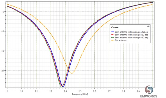
Figure 6 - The simulated return loss S11 for each configuration.
After bending, the resonant frequencies shift to approximately 2.37 GHz, outside the Bluetooth band, indicating a notable impact of bending on the antenna's resonance frequency performance. Figure 7 showcases the gain pattern of various configurations, revealing an omnidirectional pattern across all configurations. However, the flat antenna exhibits the highest gain value.
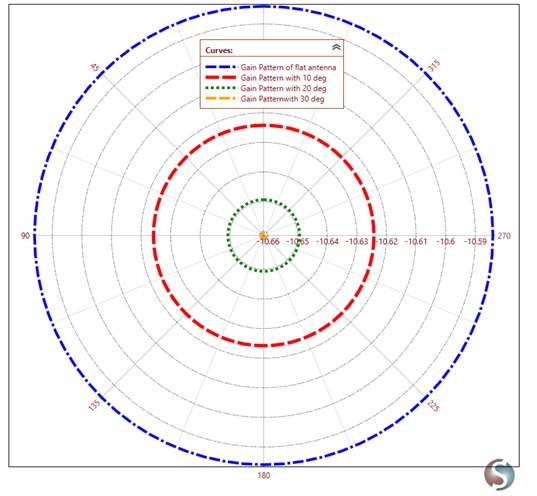 Figure 7 - The gain pattern of each configuration
Conclusion
Efficient antenna design is crucial for enhancing the performance of Bluetooth-enabled smartwatches. Through HFWorks simulation, we've explored the intricacies of both flat and bent antenna configurations, shedding light on resonance frequencies, return losses, and gain patterns. These insights are invaluable for designers seeking to optimize antenna performance for wearable electronics. By leveraging simulation tools like HFWorks, manufacturers can ensure that Bluetooth antennas deliver reliable connectivity and seamless user experiences in the rapidly evolving landscape of wearable technology.