| Transformer Simulation - Perform Open and Short Circuit Tests Easily Using EMS inside SOLIDWORKS
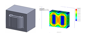
The objective of a good design is to reduce the losses in the transformer. Once a transformer is designed, engineers build a prototype and then measure the losses using open circuit and short circuit tests. Also, these tests enable engineers to create an equivalent circuit of a transformer. Once you have the equivalent circuit of a transformer it is very easy to replace the transformer by its equivalent circuit and perform system level simulation. The interesting feature about simulation in EMS is the ability to perform both the above-mentioned tests virtually inside SOLIDWORKS. In this example, a single phase transformer with a core loss material is simulated using EMS (Figure 1). Figure 2 shows the magnetic flux density inside the transformer. The core loss and the other losses quantities are generated in the results table of EMS. The deducted equivalent circuit of the simulated transformer is presented in the Figure 3.
Simulation of a Circularly Polarized Feedhorn
This example presents a validated HFWorks simulation of a high efficiency horn antenna which is intended to illuminate a passive parabolic reflector. Originally, the design uses two waves with different modes and provides exceptional clean radiation patterns. A one-wave-model is simulated to test the return loss match. The radiation patterns results are shown as well as the inner electric field distribution. The electric field distribution is plotted in the Figure 1 in a section view. The plot in the Figure 2 shows the return loss from 1.1 GHz to 1.5 GHz. The minimum is attained at approximately 1.29 GHz. The figure 3 illustrates the radiation patterns of the antenna, it shows a perfect agreement with the measured results.
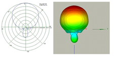
Figure 3 : Radiation patterns at 1.296 GHz simulated in HFWorks.
Read more
Science News
Scientists Use EEG Machine to Create Digital Images From Brain Activity
Building on previous research that used FMRIs to digitalize what faces look like when imagined by the human mind, a team of researchers has done the same with EEG machines — a cheaper and more commonplace option.

Read full article |
|
Figure 1 : 3D Model of the transformer.
|
Figure 2 : section plot of the magnetic flux density in the core of the transformer.
|
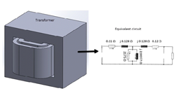
Figure 3: Equivalent circuit of the transformer
Read more
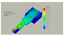
Figure 1: Electric field distribution
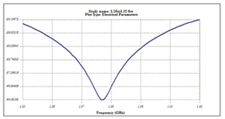
Figure 2: Return loss computed by HFWorks
Read more
Blog Post
How to Setup your SOLIDWORKS Model to Perform a Coupled Electro-Magnetic and Motion Simulation
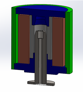
Figure 1: Section view of a linear actuator to be simulated using coupled Motion and EM simulation.

Figure 2: Magnetic flux density and dynamic response.
Read more |