| Electrothermal Simulation of an Electric Fuse Application
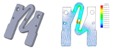
EMS allows coupled electromagnetic and thermal fields analyses. This coupling is ensured without the need to export and import any kind of results. This example illustrates the use of the capability of EMS to model the heating of an automotive electrical fuse (Figure 1). They are the primary circuit protection devices in automobiles. They are available in different ranges of current ratings and are designed so that when the operating current exceeds the fuse 's characteristic value for a period, heating due to electrical conduction causes the metal conductor to melt and—hence—the circuit to disconnect. Electric conduction module is used to compute the current distribution in the fuse as shown in the Figure 2. Electrical results are transferred to the thermal solver. Figure 3 shows the temperature distribution in the electric device generated by EMS coupled to thermal analysis.
|
Figure 1 : 3D model of an automotive
|
Figure 2 : Current density distribution in the fuse
|

Figure 3 : Temperature distribution in the fuse
Read more
Science News
AI Will Lead the Charge Developing Quantum Computers
Although quantum physics deals with the "physics of the small," measuring quantum systems is no small feat. To make things simple, researchers turned to artificial neural networks and machine learning.
 Read full article
 |
Design and simulation of Single-band Planar Crossover based on Coupled Line
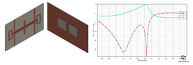
HFWorks is an antenna and electromagnetic simulation software for RF, Microwave, mm-wave, and high frequency and high speed electrical and electronics devices and circuits. In this article, a compact single planar crossover based on coupled lines is designed using SOLIDWORKS and simulated using the full wave 3D simulator HFWorks (Figure 4). An S Parameters analysis is conducted to characterize the electromagnetic behavior of this structure. The simulated S parameters results S11 and S31 using HFWorks and the measured results of the single band crossover are depicted in Figure 5. The S Parameters are shown from 0.5 GHz to 3.5 GHz. the central frequency is located around 1.8 GHz. HFWorks automatically computes the electromagnetic field. The distribution of the electric field at the resonance frequency is shown in Figure 6. The incident power is 1W.
|
Figure 4 : The 3D SOLIDWORKS Model of the compact planar crossover
|
Figure 5 : The return loss S11 measured and simulated results
|
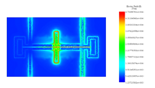
Figure 6 :Distribution of the electric field at 1.80 GHz
Read more
Blog Post
Parametric EM simulation in SOLIDWORKS
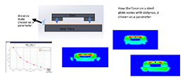
Figure 7 : Force on a steel plate as a function of the distance between the plate and the magnet arrangement
Read more |