|
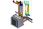
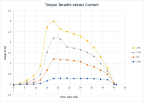
This example shows the analysis study for a 6/4 switched reluctance motor, shown in the following figure, using EMS for Autodesk Inventor. The stator and rotor cores are both made of non-oriented M-19 silicon steel. The 4-phase windings are made of copper, and each winding has 120 turns per coil. To compute the electromagnetic torque, a parametric study was defined; in this study the torque generated by one stator phase around one rotor pole was computed. Therefore, the rotor of the switched reluctance motor was displaced to a total of 46 degrees from the unaligned position (0 deg) to the aligned position (46 deg).
|


-0-deg-b)-18-deg-c)-46-deg.png)