 |
APPLICATION NOTE
DESIGN AND SIMULATION OF A BLUETOOTH ANTENNA FOR WEARABLE DEVICES USING HFWORKS
|
|
Wearable technology is often mirrored as one of the greatest applications of the Internet of Things (IoT). This branch of smart electronics is the epitome of
emerging IoT applications. Nowadays, smart watches are one of the most common wearable devices. Usually, the Bluetooth protocol is used to secure connection between the smart watch and another device.
In this article, a Bluetooth antenna for smart watches
is designed with SOLIDWORKS and simulated using the full wave simulator HFWorks. Two configurations of a flat and bent Bluetooth antennas will be demonstrated to compare the electromagnetic behavior in both cases. The Antenna analysis of HFWorks was used to simulate these antennas.
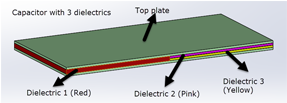
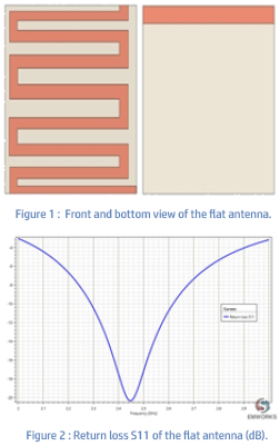
Figure 1 shows the confifiguration of flflat Bluetooth antenna structure. The overall size of this antenna is , and it operates at 2.45 GHz. This antenna is excited using microstrip line with an impedance of 50 Ohm. The used materials are FR4 with a relative permittivity of 4.5, and the metals are considered as perfect electric conductor (PEC).
|
|
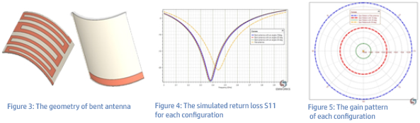
For wearable electronics, it is important to study the performances of the antenna under
various bending conditions. Different configurations with SOLIDWORKS will be presented by
varying the bending angle. Figure 3, shows the geometry of the bent Bluetooth antenna.
Different bending angles are simulated and compared using the multi configurations feature
inside SOLIDWORKS.
The simulated return losses S11 for each confifiguration are given in Figure 4. Obviously, the
bending angle has a knock-on effect on the resonant frequency of the antenna. The resonant
frequencies after bending are around 2.37 GHz, which is outside of the Bluetooth band;
implying that the bending affects the performance of the antenna in terms of resonance
frequency. The gain pattern of different configurations is displayed in Figure 5. The gain
pattern for all the configurations maintains an omnidirectional pattern, however, the flat
antenna has the highest value.

THERMO-STRUCTURAL BEHAVIOR OF THREE-PHASE BUSBAR SYSTEM UNDER AC MAGNETIC REGIME
The aligned arrangement of busbars carrying high current causes their resistance to rise. It is
essentially due to both skin and proximity effect between busbars, which directly increases their
thermal stresses. Therefore, a numerical modeling of the thermal and mechanical behavior of a
three-phase busbar system is investigated using EMS simulation tool. The AC magnetic module
coupled to both the steady state thermal and structural analysis is used to compute and visualize
the temperature and deflection distribution for each phase conductor.
|
|
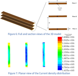
In this analysis, the considered busbar system
is made of a three-phases arrangement with a
single copper conductor for each phase,
separated by an equal isolation distance (D).
The isometric and cross sectional view of the
model are shown in the Figure 6.
The Multiphysics simulation revealed the
results below. Figure 7 shows the current
density distribution across each conductor for
the phase . It reaches a maximum peak value of
3.83E+06 A/m² (RMS value 2.7E+06 A/m² ).
An unbalanced current distribution can clearly
be noticed among the three conductors; this is
due to the proximity effect and the 120°
phase shifting.
|
|
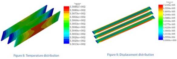
The attained temperature, generated by Joule effect phenomenon is shown in the Figure 8. It
achieves an average value of 330K for each conductor of the busbar system. The mechanical
displacement of the busbar conductors generated by thermal stress, is also evaluated under
AC regime. It reaches maximum values within the lateral faces of the busbar conductors. The
Figure 9 shows the resultant displacement plot across the busbar system.
|
FIND US AT |
MOTOR & DRIVE SYSTEMS 2019
DESIGNCON 2019
SOLIDWORKS WORLD 2019
|
January 22-24, 2019, ORLANDO, FLORIDA, Booth #117
January 29-31, 2019, SANTA CLARA, CA, Booth #955
February 10-13, 2019, DALLAS, TEXAS, Booth #807
|
|
|