 |
 |
|
EMWorks invites you to Montreal to attend our annual user conference. The event is a unique opportunity to learn more about your simulation tools in a relaxed and interactive environment and reconnect with the rest of the EMWorks community. Whether you come from industry or academia, whether you are an advanced user or just getting started, you will benefit from attending.
|
Application Note
THERMO-STRUCTURAL BEHAVIOR OF RF MICROWAVE POWER DIVIDER
|
|
Radio frequency (RF) and microwave systems typically require a perfect power distribution networks performed through two types of microwave structures: Dividers to split an input signal into two or more output signals and Combiners to associate RF input signals from multiple inputs into single RF output signal. At high power average level, waveguide-based structures are commonly used for a wide variety of multi-port power dividers/combiners. The studied WG power splitter, proposed in this study, is the Folded H plane tee junction. It is a three-ports divider in which its output and input arms are implemented in a single plane along a single axis, thus taking less space in the overall system.
The proposed Waveguide power divider is made of 3 ports. It allows to split the input power into two equi-phasic and equi-amplitude signal outputs. The 3D geometrical structure of the outer copper housing with its air cavity are shown in Figure 1.
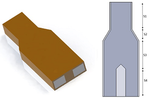
Figure 1 - The 3D design of the studied power divider
|
|
The S-parameters solver of HFWorks is used, coupled to the thermal and structural cases for a working frequency range of [3.45GHz-3.9GHz]. The electric field distribution versus phase is presented by the Figure 2. It is showing an excellent power division at 3.7GHz.
The frequency response of the splitter is depicted in the next 2D plot (Figure 3) of the return and insertion losses (S11-S21) results. It shows an acceptable response under -20dB for a bandwidth of 140 MHz centered around 3.7GHz.
|
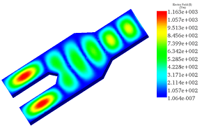
Figure 2 - Electric field distribution
|
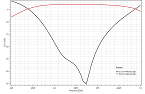
Figure 3 - Return and insertion loss results versus frequency
|
|
|
A steady state thermal analysis of the power splitter was performed at the resonant frequency of 3.7GHz. For an input power excitation of 500kW applied to the input port ,the temperature distribution across the metallic housing is shown by figure 4; it achieves a maximum value of 573°C crosswise the output arms. This temperature rise cannot be tolerated in the structure; it affects the safety of its handling and reduces its electromagnetic performance.
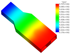
Figure 4 - Temperature distribution at 3.7 GHz
|
|
The Thermal solver feeds the thermal loads to the Structural solver which computes the final stress and displacements that affects the electromagnetic behavior of the splitter while considering the applied structural constraints.
Figure 5 is showing the thermal Von Mises stress distribution across the metallic part. the maximum stress obtained at certain points is 3.72 E+9 N/m² and the maximum deformation is up to 1.2mm (Figure 6).
|
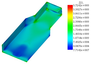
Figure 5 - Von Mises stress distribution
|
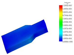
Figure 6 - Mechanical displacement animation
|
|

SCIENCE NEWS
Permanent liquid magnets have now been created in the lab
These droplets have the mechanical properties of liquids and the magnetic properties of solids
|
|
The rules about what makes a good magnet may not be as rigid as scientists thought. Using a mixture containing magnetic nanoparticles, researchers have now created liquid droplets that behave like tiny bar magnets.
Magnets that generate persistent magnetic fields typically are composed of solids like iron, where the magnetic poles of densely packed atoms are all locked in the same direction (SN: 2/17/18, p. 18). While some liquids containing magnetic particles can become magnetized when placed in a magnetic field, the magnetic orientations of those free-floating particles tend to get jumbled when the field goes away — causing the liquid to lose its magnetism.
|

MAGNETIC DROPLETS Scientists have now created permanent liquid magnets. Here, magnetized liquid droplets (yellow) twirl in oil, under the influence of a rotating magnetic field, wrapping themselves in orange dye.
|
Customer Testimonial
| “ |
My First impression of HFWorks right out of the gate was, “ Brilliant”. Having HFWorks integrated directly into SolidWorks saves me so much time when it comes to building and testing coaxial RF connectors. I was very impressed with one click I was able to obtain TDR results of my RF model which really gives me everything I am looking for, especially when other software like HFSS makes it such a pain to get similar results.
— John Lomba, a student,University of Massachusetts Lowell
|
WEBINARS
|

|
Electromagnetic Modeling with EMS for SOLIDWORKS - A Quick Walk Through
|
Wednesday, September 11, 2019
02:00 PM EST
|
 |
|
EVENTS

|
Electric & Hybrid Vehicle Technology 2019
SEPTEMBER 10-12 - Novi, MI
Visit us at Booth #1526.
|
|
|
|
|