 |
 |
|
EMWorks invites you to Montreal to attend our annual user conference. The event is a unique opportunity to learn more about your simulation tools in a relaxed and interactive environment and reconnect with the rest of the EMWorks community. Whether you come from industry or academia, whether you are an advanced user or just getting started, you will benefit from attending.
|
Application Note
MAGNETIC GEAR: 2D FEM SIMULATION WITH EMWORKS2D INSIDE SOLIDWORKS
|
|
Finite element method (FEM) has demonstrated high reliability in the design and analysis of engineering systems [1]. It can be used to simulate any complicated geometry and for both linear and nonlinear problems. Moreover, Finite element analysis (FEA) can be used to solve both 3D and 2D approximated geometry. Additional advantages are gained when using 2D FEA such as saving time, running more iterations, etc. EMWorks2D, which is a 2D FEM plug-in inside SOLIDWORKs, provides an accurate solution to magnetic and electric problems in cases where the real-life problem can be approximated as a 2D problem.
In this article, EMWorks2D is used to compute magnetic results (magnetic flux density, field intensity, torque, etc.) of two coaxial magnetic gear models. The torque generated by both configurations will be predicted and investigated. Both results will be compared to the reference results.
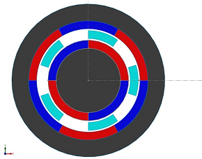
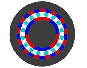
The simulated models are shown in Figure 1. Model 1 has a smaller number of poles than model 2. In both cases, the inner rotor rotates with higher speed and develops lower torque.
|
 (a) (a)
|
 (b) (b)
|
Figure 1 - Simulated magnetic gear, a) model 1, b) model 2
|
|
Figure 2 contains contour lines plot of the magnetic vector potential generated inside the first model while Figure 2 illustrates the torque created in the inner rotor versus rotor angle of the same model (outer rotor and ferromagnetic pieces are fixed).
|
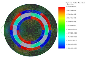
Figure 2 - Magnetic vector potential lines plot
|
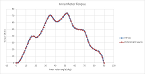
Figure 3 - Inner rotor torque
|
|
|
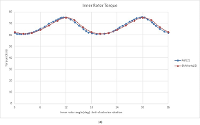
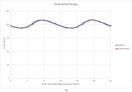
The following figures give the torque results of inner and outer rotor of both models (inner and outer rotors are rotating in opposite direction). For model 1, The average torque results are 67 N.m and 101 N.m respectively of the inner rotor and outer rotor (Figure 4). It can be concluded that the gear ratio is 1.5. It can be computed also using the pole-pairs number of the inner and outer rotors.
|
|
Figure 4 - Torque results model 1, a) inner rotor, b) outer rotor
|
|
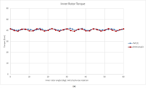
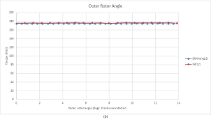
The torque results of model 2 are shown in Figure 5. The HS rotor develops a torque of 41 N.m while the generated torque in LS rotor is about 175 N.m. Thus, both torques verify a gear ratio of 4.26 and are characterized by lower ripples. As can be seen from Figure 5b), the ripples are practically eliminated.
|
|
Figure 5 - Torque results model 2, a) inner rotor b) outer rotor
|

SCIENCE NEWS
New ways to construct contactless magnetic gears
|
|
The new milk frother you are using to prepare your cappuccino is likely using magnetic gears. Magnetic gears transmit rotary motion like mechanical gears but instead of teeth they use magnetic attraction and repulsion between rotating magnets. Dr Johannes Schönke, a postdoctoral scholar at the Okinawa Institute of Science and Technology Graduate University (OIST), published in Physical Review Applied a theory which extends the possibilities and applications for smooth magnetic couplings, which can produce an even motion without any counterforce. This research has several potential applications in nanotechnology, microfluidics and robotics
|
Source: Okinawa Institute of Science and Technology Graduate University – OIST
|
WEBINARS
|

|
Electromagnetic Modeling with EMS for SOLIDWORKS - A Quick Walk Through
|
Monday, Sep 16, 2019
02:00 PM EST
|
 |
|
EVENTS

|
Electric & Hybrid Vehicle Technology 2019
SEPTEMBER 10-12 - Novi, MI
Visit us at Booth #1526.
|

|
ECCE 2019
SEP 30, 2019 To Oct 1, 2019 - Baltimore, MD
Visit us at Booth #801.
|

|
INMR 2019
Oct 21-23, 2019 - Arizona, USA
Visit us at Booth #75.
|
|
|
|
|