 |
Application Note
ELECTROMAGNETIC SIMULATION OF BRUSHLESS DC MOTOR INSIDE SOLIDWORKS
|
|
In this article, a BLDC motor has been created and simulated using, respectively, SOLIDWORKS and EMWorks2D (see Figure 1). The proposed model has been studied in [1]. The BLDC model is automatically generated using MotorWizard. It is a motor software provided by EMWorks allowing both automatic design and simulation of electric motors. In addition to MotorWizard, EMWorks provides a 2D electromagnetic software (EMWorks2D) utilizing finite element method (FEM) and integrated inside SOLIDWORKS. In this application, EMWorks2D is used to compute magnetic results (magnetic flux density, field intensity, torque, inductances, flux linkage, etc.) of the simulated example. Torque results versus both rotor position and ampere-turns will be compared to reference results.
Figure 1 contains the 2D geometry of the simulated BLDC motor [1]. It consists of a 3-phase machine with 12 slots and 6 poles. stator and rotor cores are made of steel (1000 as relative permeability). The rotor poles, having surface mounted structure, are made of ferrite permanent magnets (Br=0.4T). The shaft has non-magnetic material. The double layers windings are arranged on 3 phases with a coil pitch equal to 1. Each phase has 1456 turns. The excitation currents versus rotor position are shown in Figure 2.
|
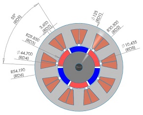
Figure 1 - 2D model of the BLDC motor
|
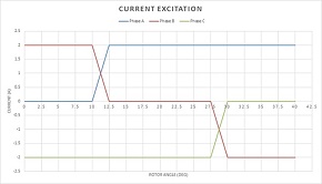
Figure 2 - Excitation currents
|
|
|
Figures 3a) and 3b) give respectively fringe and vector plot of the magnetic flux distribution inside the motor.
|
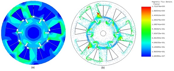
Figure 3 - Magnetic flux, a) fringe plot b) vector plot
|
|
|
Figure 4 superimposes fringe plot of the magnetic flux density and the magnetic vector potential contour lines.
|
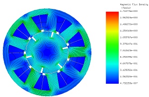
Figure 4 - Flux lines
|
|
The figure below shows the load torque results computed by EMWorks2D for an angle range from 0 deg to 40 deg and compares them with the presented results in [1]. The torque curve is characterized by small ripples amplitude but considerably a high number of ripples (totally 18 ripples in one full revolution). The maximum and the minimum values of the computed torque are respectively 2.05 N.m and 1.53 Nm. The average developed torque is around 1.89 Nm. Figure 6 shows the torque evolution versus the ampere-turns. It is proportional to the excitation. This linear dependency of the static torque generated by the BLDC is considerate as an advantage of brushed DC motor. Hence, it is an inherited advantage to the BLDC without using commutators and brushes.
|
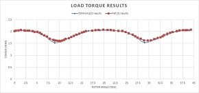
Figure 5 - Torque results versus rotor angle
|
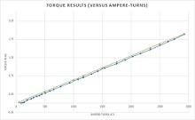
Figure 6 - Torque results versus ampere-turns
|
|
[1]: G. M’boungui, E. K. Appiah, A. A. Jimoh, T. R. Ayodele. Simple Numerical Two-Dimensional Magnetostatic Analysis of a Fractional Slot Winding Brushless DC Motor. Proceedings of the World Congress on Engineering and Computer Science 2013 Vol I WCECS 2013, 23-25 October, 2013, San Francisco, USA
|
|

SCIENCE NEWS
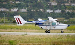
By Air, Land and Sea, Travel is Electrifying
The roar of a jet engine, the vroom of a car, the vibration of a moving ship.
|
|
These sounds and sensations, commonly associated with travel and motion, share a common source: fossil fuel-powered engines.
But as regulators and businesses around the world try to reduce carbon emissions, airplanes, automobiles and ships are going electric. It’s good for the environment, but it also means travel itself may be changing. Here’s a look at a few of the initiatives that are underway.
|
|
EVENTS

|
INMR 2019
Oct 21-23, 2019 - Arizona, USA
Visit us at Booth #75.
|

|
DesignCon 2020
January 28-30 - Santa Clara, California
Visit us at Booth #1153.
|

|
Motor & Drive Systems 2020
February 11-12, 2020 - Orlando, FL
Visit us at Booth #303.
|
|
|
|
|