A MEMS Micro-Gripper
MEMS microgrippers offer exceptional adaptability and versatility across various engineering fields, including micromanipulation tasks and micro-assemblies. These integrated grippers undergo multiphysics analyses to explore their mechanical manipulation capabilities under low power consumption.
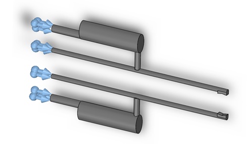
The micro-gripper under examination (seen in Figure 1) features two gripping tips connected to U-shaped actuators. Designed to securely hold micro-objects, this device deflects its arms when subjected to a DC voltage. Through detailed analysis, researchers aim to unravel the mechanisms driving the microgripper's functionality and its potential applications in precision engineering.
![The studied micro-gripper holdding a ball between its both tips [1]](/ckfinder/userfiles/images/The-studied-micro-gripper-holdding-a-ball-between-its-both-tips%5B1%5D.jpg)
Figure 1 - The studied micro-gripper holding a ball between both tips [1]
CAD Model
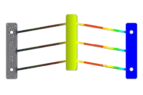
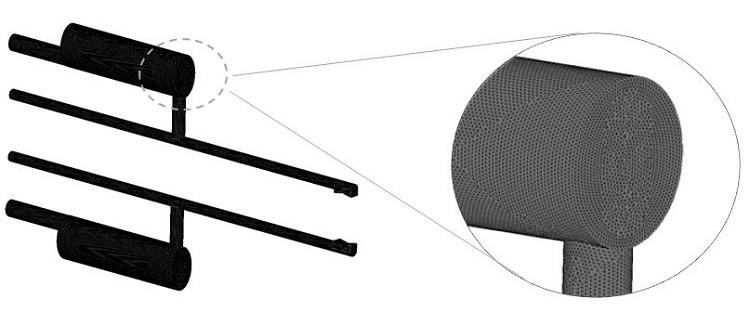
The micro-gripper's performance is modeled using the EMS finite element tool to estimate its displacement and temperature distribution. The schematic illustration and 3D model are depicted in Figure 2.
![Schematic illustration of the micro-gripper [1] a). 3D Model b).](/ckfinder/userfiles/images/Schematic-illustration-of-the-micro-gripper-%5B1%5D-a%29.-3D-Model-b%29..jpg)
Figure 2 - Schematic illustration of the micro-gripper [1] a). 3D Model b).
Table 1 - Model dimensions [1]
| Parameter | Symbol | Value (mm) |
| Length of the hot arm Width of the hot arm Thickness of the hot arm | \( L_h \) \( 2_a h \) \( 2_b h \) | 4.5 0.21 0.21 |
| Length of the intermediate arm Width of the intermediate arm Thickness of the intermediate arm | \( L_i \) \( 2a_i \) \( 2b_i \) | 0.8 0.27 0.25 |
| Length of the cold arm Width of the cold arm Thickness of the cold arm | \( L_c \) \( 2a_c \) \( 2b_c \) | 3 0.9 0.63 |
| Length of the flexure arm Width of the flexure arm Thickness of the flexure arm | $$ L_f $$ $$ 2a_f $$ $$ 2b_f $$ | 1.5 0.35 0.3 |
| Total length | $$ L $$ | 9 |
| Initial gap | $$ g $$ | 1 |
Simulation Setup
The Magnetostatic module of EMS, integrated with thermal and structural analysis, accurately predicts and evaluates the thermal and mechanical characteristics of the microgripper.
The simulation setup involves several key steps:
1. Material selection: Choosing suitable materials for the microgripper components.
2. Electromagnetic input definition: Defining parameters related to electromagnetic properties.
3. Thermal input definition: Specifying thermal properties and boundary conditions.
4. Structural boundary conditions application: Implementing constraints to simulate real-world operating conditions.
5. Mesh generation and solver execution: Creating a mesh for the entire model and running the solver to obtain results.
Materials
In our case study, we utilize the material properties listed in Table 2 to characterize the materials employed in the microgripper design.
| Property | Density (Kg/ $$m^3$$) | Electrical conductivity (S/m) | Thermal conductivity (W/m. K) | Thermal expansion coefficient (/K) | Elastic Modulus (GPa) | Poisson’s ratio |
| Silver-Nickel Composite (Ag-Ni) | 2370 | 31903 | 66.7 | 120 E-06 | 21.5 | 0.3 |
Electromagnetic Input
Each extended tip of the micro gripper is designated as a solid coil carrying a voltage of 1.54 V, with the entry/exit port illustrated in Figure 3.
Thermal Input
A thermal boundary condition of 27°C is applied to both anchored pads, while thermal convection is implemented on the air body at ambient temperature, with a coefficient set to 10 W/m²K.
Structural boundary condition
Fixed boundary conditions are applied to both sides of the anchored pads, as depicted in Figure 4.
Meshing
The entire model is meshed within EMS using a finely controlled mesh, as illustrated in the figure below, to ensure more accurate results.
Results
The simulation results unveil the following findings. Figure 6 illustrates the maximum temperature distribution, occurring at the hot arm, corresponding to an input current value of approximately 0.26 A.
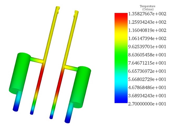
In terms of mechanical displacement, each extended tip attains a maximum deflection of 166 µm.
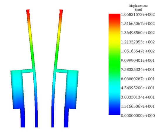
For the identical input applied voltage, Table 3 provides a comparison between the measured and simulated results provided by the reference [1] and the EMS tool.
| Results | Simulation [1] | Measurement [1] | EMS |
| Max total Displacement (µm) | 322 | 311 | 332 |
| Max Temperature (°C) | 155 | 123 | 135 |
Conclusion
The application note on a MEMS microgripper showcases the device's adaptability and versatility in precision engineering tasks such as micromanipulation and micro-assembly. Utilizing low power consumption, the microgripper, equipped with two gripping tips connected to U-shaped actuators, demonstrates significant mechanical manipulation capabilities. Through the application of a DC voltage, the arms of the microgripper deflect, enabling the secure handling of micro-objects. This study leverages the EMS finite element tool for simulating the micro-gripper's displacement and temperature distribution, providing a detailed insight into its operational mechanisms. The simulation results, corroborated by comparison with reference data, reveal a maximum temperature increase at the hot arm and a significant deflection of 166 µm at each extended tip, indicating the microgripper's efficient performance. This research underlines the potential of MEMS microgrippers in enhancing the precision and efficiency of micro-scale engineering operations, offering a promising solution for complex micromanipulation tasks.
References
[1]. Feng, Yao-Yun, et al. "Fabrication of an electro-thermal micro-gripper with elliptical cross-sections using silver-nickel composite ink." Sensors and Actuators A: Physical 245 (2016): 106-112.