 |
 |
Application Note
HOW EMS AND SOLIDWORKS MOTION CAN HELP TO DESIGN AND ANALYZE EDDY CURRENT BRAKES
|
|
In this application note, rotary eddy currents brakes (ECB) will be studied using EMS inside SOLIDWORKS. EMS couples electromagnetic solution with SOLIDWORKS motion to solve electromechanical problems. The simulated model is made of two non-touched components: a rotating copper disk, fixed arrangement of permanent magnets and back iron core.
Constant speed (steady state)
In this case, the disk is being rotated with a constant angular speed (1000 rpm anti-clockwise). Eddy currents, generated in the copper disk, will create an electromagnetic torque acting in the reverse direction to the motion. Figure 2 shows fringe plot of the magnetic flux density in the permanent magnets and the iron core. The iron core is used to reduce the magnetic flux losses and to orient the field to the direction of the disk. H field plot is shown in Figure 3.
|
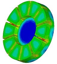
Figure 2 - Magnetic flux distribution
|
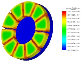
Figure 3 - H field density
|
|
|
Figures below illustrate the eddy current distribution inside the copper disk. they show several loops of current facing each magnet pole and their directions depend on the magnetization direction of the magnets.
|
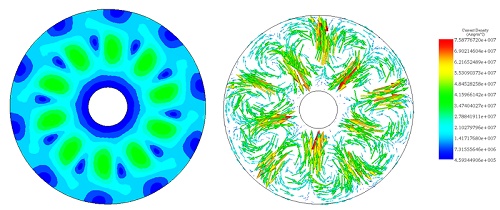
Figure 4 - Eddy current distribution in the copper disk
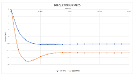
Figure 5 - Generated torque for different speed rate
|
Deceleration phase
In this section, the braking phase (disk deceleration) is studied. Initially, the disk is rotating with the speed of 1000 rpm, the load torque is suppressed, and the braking torque is applied to slow down the disk. Figures below demonstrate the eddy current distribution at different time steps i.e different instantaneous speeds. The eddy current density is decreasing with speed.
|
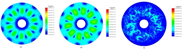
Figure 6 - Eddy current distribution, a) at 0.005s b) at 0.05 c) at 0.17s
|
|
Figure 7 superimposes the curve of the electromagnetic torque and the disk angular speed. It shows that the torque, generated by eddy currents in the disk, is increasing while the speed is decreasing until 0.04s. Then, when the speed becomes low, the torque starts to decrease. After reaching the steady state (0.1s), both electromagnetic torque and speed are close to zero.
|
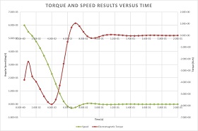
Figure 7 - Braking torque and angular speed curves
|

SCIENCE NEWS
Using Electromagnetic Brakes to Keep Thrust Reversers IN PLACE
|
|
Applying reverse thrust redirecting engine power to oppose the direction of travel is a standard technique for decelerating aircraft after touchdown. The approach saves wear on the brakes of the landing gear wheels and reduces stopping distance. Although accidental deployment of the thrust reverser cowl could and did happen, it was assumed for decades that this would only present a hazard in the moments around takeoff and landing. With changes to engine design and aircraft aerodynamics, this assumption no longer held, as demonstrated by the catastrophic loss of Lauda Air Flight 004.
|

|
EVENTS

|
DesignCon 2020
January 28-30 - Santa Clara, California
Visit us at Booth #1153.
|

|
3DEXPERIENCE World 2020
February 9-12, 2020 - Nashville, TN
Visit us at Booth #428.
|

|
Motor & Drive Systems 2020
February 11-12, 2020 - Orlando, FL
Visit us at Booth #303.
|
|
|
|
|