What is a bandpass filter and what are its applications?
A bandpass filter acts like a security gatekeeper, allowing only signals within a specific frequency range to pass, blocking all others. This is crucial for wireless communication devices to filter out unwanted frequencies. For example, a wideband bandpass filter used in a wireless receiver might operate between 2 and 6 GHz, ensuring only relevant signals are processed. Below is a design of such a filter.
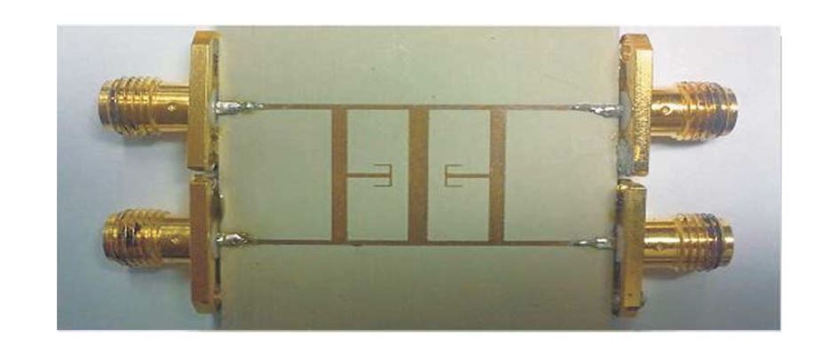
Figure 1 – Wideband Bandpass Filter
Simulation results
Scattering parameters, or s-parameters, are crucial for characterizing RF and microwave devices. Electronics engineers utilize the s-parameter matrix from their designs to construct complex circuits with passive components. HFWorks simplifies this process by automatically computing and outputting the s-parameter matrix. Additionally, HFWorks can compute other key metrics such as the Impedance matrix and VSWR. Figure 2 illustrates the s-parameters calculated by HFWorks for a wideband bandpass filter.
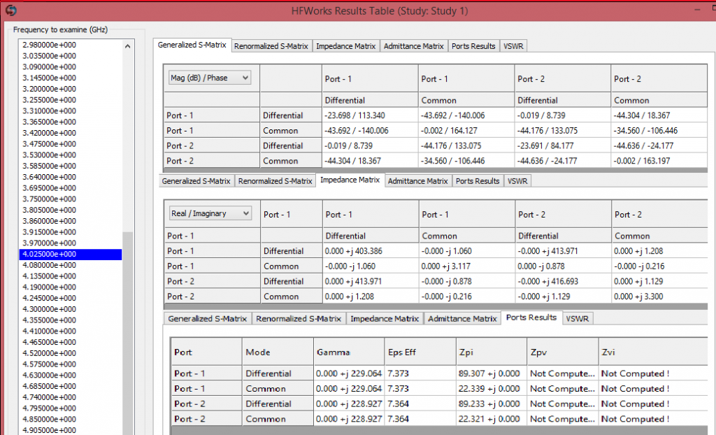
Figure 2 - HFWorks gives all engineering details including s-parameters in a Result Table
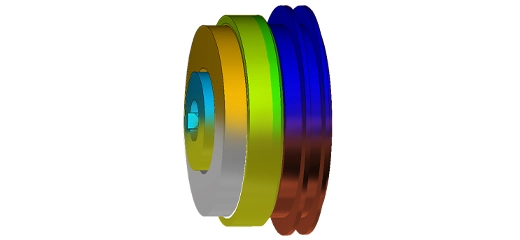
HFWorks is a 3D field simulation software that enables users to visualize results such as electric and magnetic fields in three dimensions. For instance, engineers can examine the electric field distribution within their filter, as depicted in Figure 3. This 3D visualization helps identify areas within the model where electric field strength is high. Additionally, users can create section plots to further analyze electric field results inside their designs.
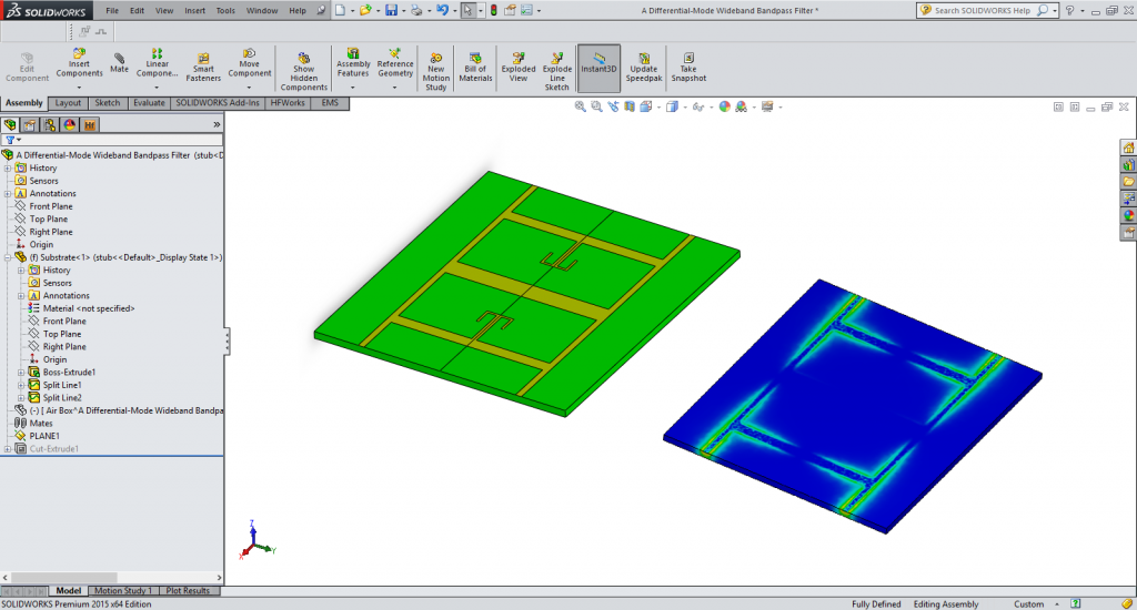
Figure 3 - Electric field distribution inside the filter
HFWorks in action
Watch a quick video showing how HFWorks allows electronic designers to analyze their passive RF and Microwave components.
[embed]https://www.youtube.com/embed/znZMpQJivGQ[/embed]Learn more about HFWorks
HFWorks stands out as the first and only high-frequency electromagnetic software embedded in CAD, specifically tailored for studying passive RF and microwave component designs directly within the CAD environment. It seamlessly utilizes CAD-created geometry for simulations, eliminating the need for geometry transfer. HFWorks' user interface mirrors that of CAD, offering a familiar experience without any learning curve for CAD users. For information on trials, benchmarks, and pricing for HFWorks, and to see how it can enhance your product design, please feel free to contact us.
Conclusion
HFWorks offers a robust solution for engineers looking to enhance their design process for RF and microwave components within the CAD environment. By seamlessly integrating with CAD software, HFWorks not only simplifies the workflow but also improves the accuracy and efficiency of simulations. This tool is essential for anyone aiming to optimize the performance and reliability of their designs through precise electromagnetic simulations and detailed analysis of parameters like S-parameters and electric field distribution. Whether you're designing filters, antennas, or resonators, HFWorks provides the tools you need to succeed in a competitive market.