What is Switched Reluctance Motor?
Switched reluctance motor “SRM” also called variable reluctance motor is gaining interest in industrial applications such as electric vehicles and wind energy systems due to its simple and rugged construction. SRMs have better efficiency, better reliability, high fault tolerance, high constant power speed ratio (CPSR), and resistance to high temperatures compared with other types of motors such as induction motors, permanent magnet synchronous motors, and brushless DC motors. The development in the power electronics converters and their latest control techniques are the main reasons for the increase in the usage of SRMs.
SRM consists of a stator and rotor cores which are made up of a stack of laminated electrical steel sheets. The coils are wound directly on the stator tooth or they can be wound on the bobbin and then inserted into the stator tooth to achieve a higher coil fill factor. The rotor with salient poles is free from the magnets and windings as shown in the figure below.

3D CAD View of 8 Slots-6 Poles Switched Reluctance Motor using EMWorks Software
In nature, either we have fluids, electric currents, or magnetic fields they all like to flow through the path of the least resistance nothing but the least reluctance path which means higher inductance. So that’s the fundamental working principle of the switched reluctance motors. The reason it is called switched is that once the stator and the rotor poles are aligned then it quickly switches to the next phase so that the rotor keeps chasing the phase that is excited as presented in the animation below. Hence the reluctance torque is developed in the rotor.
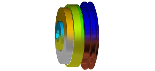
Magnetic Flux Density Plot of SRM
Key Advantages of Switched Reluctance Motor
- Simple and rugged structure
- Magnetless brushless motor
- Higher reliability and efficiency
- Reduced material cost and manufacturing time
- Less weight and reduced complexity
- Improved thermal capabilities
Design Challenges
- Construction of 2D/ 3D motor geometry for an electromagnetic, thermal, and structural analysis
- Material types, winding configuration, and its excitation setup in an FEA-based software
- Obtaining the motor static and dynamic performance characteristics such as electromagnetic torque, torque ripple, inductance vs rotor position, magnetic coil flux linkage, etc
- Estimating the core and winding losses during base speed and maximum speed operations
- Evaluating the motor characteristic during the constant torque and flux-weakening operating modes
EMWorks Solution
EMWorks suggests three electromagnetic tools that provide accurate and efficient analysis:
MotorWizard:
Is a template-based motor design software that allows users to accurately solve both electric and magnetic problems. It includes electrostatic, magnetostatic, and transient solvers equipped with integrated analytical and finite element-based solvers.
EMWorks2D:
Is a 2D electromagnetic simulation software that uses finite elements to solve magnetic, electric, and transient problems. EMWorks2D allows you to study the effects of the geometric or simulation parameter changes on the design. It also allows to couple a transient magnetic study to mechanical motion and thermal.
EMS:
Enables users to do both electric and magnetic simulations using the complete 3D geometry. EMS is a true multi-physics software that enables users to couple the magnetic, and electric design to Circuit, Motion, Thermal, and Structural analyses on the same model in a hassle-free integrated environment.
In the next analysis, MotorWizard and EMWorks2D tools will be used to investigate the SRM performance.
EMWorks Products
SRM Specifications:
The switched reluctance motor considered for analysis has 8 stator poles and 6 rotor poles made up of M27 grade steel with 0.47 mm lamination thickness. The designed motor is a four-phase machine, with a based speed of 2000 rpm and the rated peak phase current is 200 A. The mesh and specifications of the SRM are shown below.
2D Mesh of the 8 Slots-6 Poles SRM using EMWorks Software
| Specifications |
SRM |
| Configuration (slots/poles) |
8/6 |
| Based speed |
2000 rpm |
| Peak phase current |
200 A |
| Rated power |
9.64 kW |
| Average torque |
46.06 Nm |
| Stator and rotor core material |
M27 steel |
| Conductor material |
Copper |
Results
Phase-A Inductance vs. time and Rotor Angle
Static Torque vs. Time and Rotor Angle
Phase-A Coil Flux Linkage vs. Time and Rotor Angle
Energy vs. Time and Rotor Angle
From the EMWorks2D static analysis, we can observe that the value of inductance first decreases starting from 0 s to 2.5 ms and then increases from 2.5 ms to 5 ms during the simulation period. At 2.5 ms, it reaches a minimum value of 1.66 mH. This is because, at the initial position (0 s), the phase A excited stator pole and the rotor pole are fully aligned to each other, hence this leads to a maximum inductance value equal to 2.2 mH. After that, the A phase excitation will be turned off, and the next phase B will be energized. The magnetic field in the next winding will cause the rotor to rotate such that it reaches a minimum reluctance position. From the above results, we can conclude that both motor design tools MotorWizard and EMWorks2D provide users with the same and accurate results.
- On-Load Analysis – EMWorks2D
Input Current Excitation and Electromagnetic Torque Waveforms vs. Time using EMWorks2D
For on-load analysis, the SRM coils were excited with a DC square wave current characterized by a maximum value equal to 200 A. During each conduction period, only one phase is energized. The average electromagnetic torque produced by the model is almost equal to 46 Nm. However, due to the switching between the phase excitation, the SRM suffers from a high torque ripple.
- Performance Analysis - MotorWizard
Torque vs. Speed Curve using MotorWizard
As discussed above, switched reluctance motors have a high constant power speed ratio (CPSR) and high resistance to temperature. From the torque vs. speed plot obtained using MotorWizard, we can observe that the maximum speed attainable by the simulated model is up to 5-6 times the base speed during the flux weakening region.
Conclusion
In conclusion, the Switched Reluctance Motor (SRM) emerges as a highly efficient, reliable, and cost-effective solution for diverse industrial applications, including electric vehicles and wind energy systems. Its unique design, free from permanent magnets and windings on the rotor, offers significant advantages such as simplicity, durability, and exceptional thermal properties. Through the use of EMWorks' sophisticated simulation tools—MotorWizard and EMWorks2D—engineers can effectively tackle the design challenges of SRMs, optimizing their performance to meet specific application needs. These tools provide an integrated platform for comprehensive electromagnetic, thermal, and structural analyses, ensuring the development of SRMs that are not only powerful and efficient but also tailored to the evolving demands of electrification in the automotive industry and beyond.