In this blog post, we will see how HFWorks can be used to study a printed bandpass filter (BPF) centered at a frequency of 4GHz. The objectives of the simulation are 1) Finding the S-parameters for the filter and 2) Electric field distribution inside the filter
What is a bandpass filter and what are its applications?
A bandpass filter in general is an electronic device that allows signals between two specific frequencies to pass but doesn’t allow any other frequencies. Think of it as a gate keeper in a high security building where only people with an entry passcode can enter. These kinds of filters are widely used in wireless transmitters and receivers and it serves the function of a gate keeper. It limits the passage of output signal to the band accepted for transmission. So if a device is authorized to transmit say between 2 and 5 GHz, it will only allow signals within this frequency to be transmitted and all other signals will not be allowed. On the other hand if you take a receiver, it will receive all kinds of signals with various frequencies. A bandpass filter will ensure that signals within a selected range of frequency be heard or decoded. So all unwanted frequencies will be blocked. A wideband bandpass filter has a wider bandwidth and hence its name. The figure below shows a design of a wideband bandpass filter used in a wireless receiving device. It is expected to operate between 2 and 6 GHz frequency.
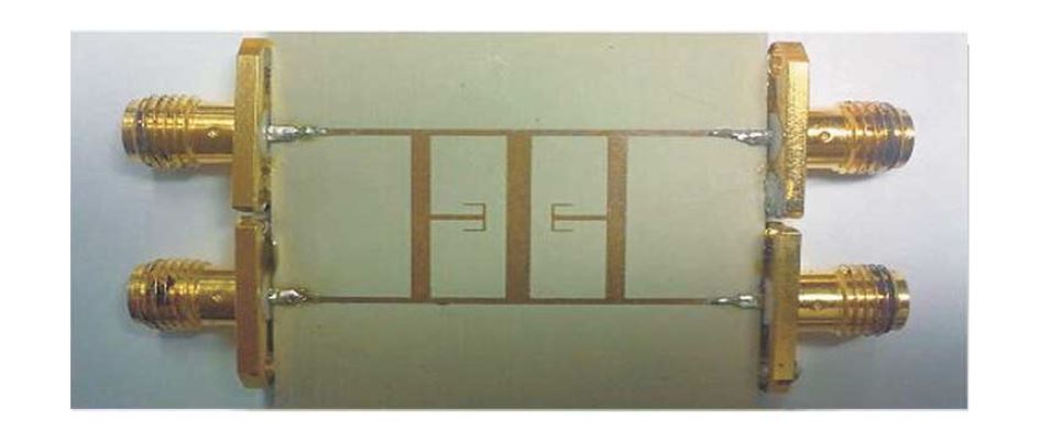
Figure 1 – Wideband Bandpass Filter
Simulation results
The scattering parameters (also called as s-parameters) are very important set of parameters that is used to characterize or describe RF and microwave devices. Electronics engineers would like to get the s-parameter matrix for their design so that they can use this information to build complex circuits using their passive components. HFWorks can automatically compute and output the s-parameter matrix. Figure 2 shows the s-parameters calculated by HFWorks for the wideband bandpass filter. In addition to the s-parameters other results like Impedance matrix, VSWR are also computer by HFWorks.
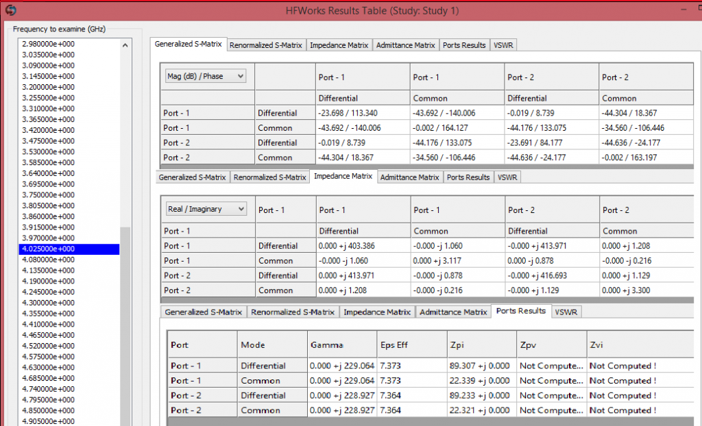
Figure 2 - HFWorks gives all engineering details including s-parameters in a Result Table
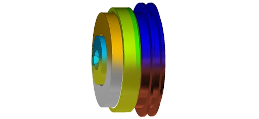
HFWorks is a 3D field simulation software and users can visualize results like electric field, magnetic field etc in 3D. For example users can see the Electric field distribution inside their filter (as shown in Figure 3). This 3D plot helps engineers to identify areas in the model where the Electric field strength are high. They can also create section plots to look at the electric field results inside their designs.
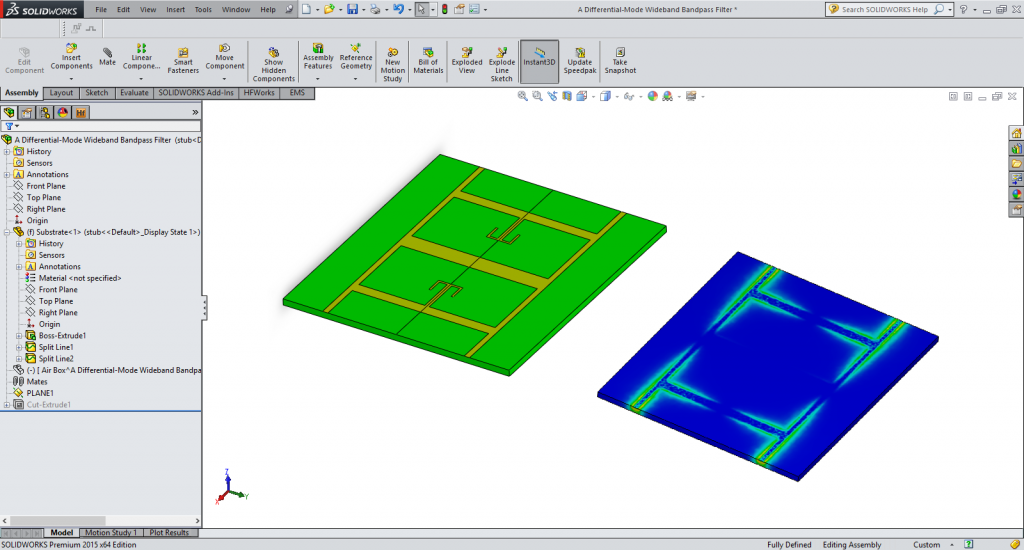
Figure 3 - Electric field distribution inside the filter
HFWorks in action
Watch a quick video showing how HFWorks allows electronic designers to analyze their passive RF and Microwave component designs seamlessly inside SolidWorks.
[embed]https://www.youtube.com/embed/znZMpQJivGQ[/embed]Learn more about HFWorks
HFWorks is the first and only Gold Certified software for SOLIDWORKS which helps SOLIDWORKS users study their passive RF and microwave component designs seamlessly inside SolidWorks. It can utilize the geometry created using SOLIDWORKS directly for simulation thus obviating the need to do any geometry transfer. Its user interface emulates the SOLIDWORKS interface and so there is no learning curve associated with HFWorks for SOLIDWORKS users. Please feel free to contact us about trial, benchmark and pricing for HFWorks and see how it helps you design better products.
Get a Benchmark or a trial
Get an analysis of your design with an HFWorks benchmark. We can test your SOLIDWORKS assembly for a variety of different applications including: antennas, connectors and transitions, Filters, passive components, resonators, transmission lines and much more.