Magnetic couplings transfer torque via magnetic fields, not physical connections, offering synchronous operation and potential 100% efficiency. They're crucial in pumps to separate motors from liquids, eliminating seal wear and leakage risks. These couplings facilitate maintenance, allow misalignments, and can serve as torque fuses. They're also applied in underwater vehicles and wind turbines for reliable, seal-free torque transfer, enhancing system longevity and safety.
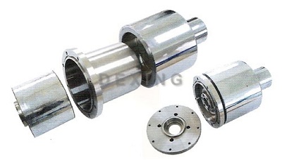
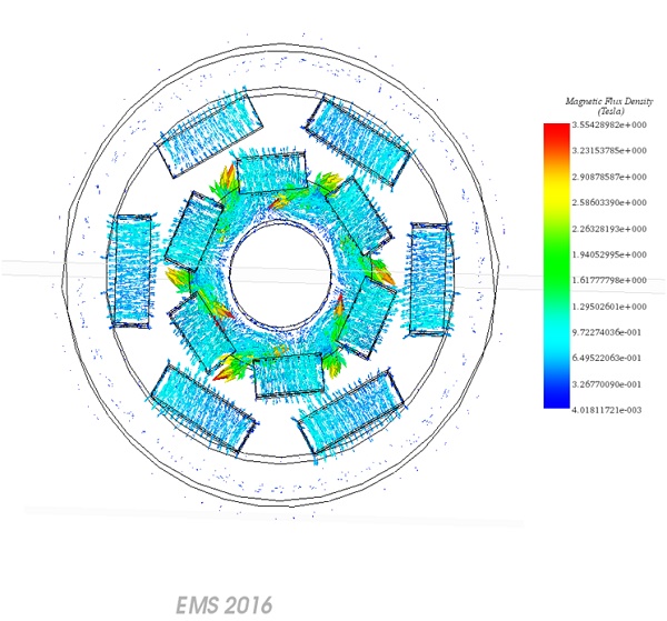
Figure 1 - Magnetic Coupling Machine
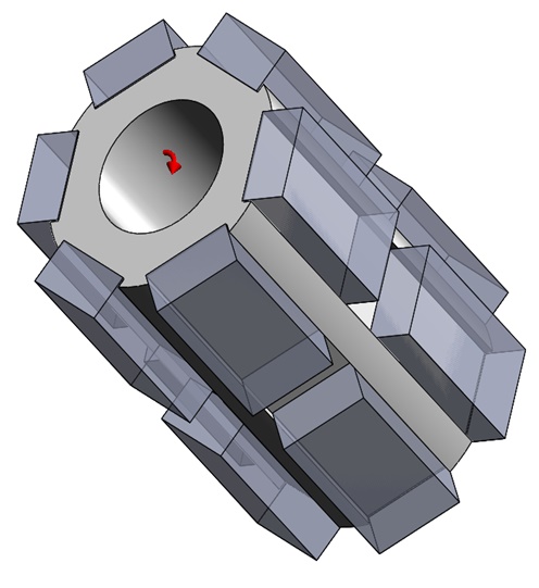
This motor utilizes a dual permanent magnet array configuration within a steel rotor and stator, each comprising 12 magnets. These magnets are arranged to alternate their polarization, facilitating both linear and rotational movement via magnetic forces. The design examines the effects of varying the angular offset between the magnet sets on the rotor's torque, revealing a direct relationship between increased offset and torque. This setup underscores the motor's efficiency in converting magnetic interaction into mechanical rotation, highlighting its potential for applications requiring precise control of movement.
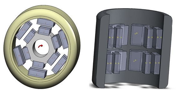
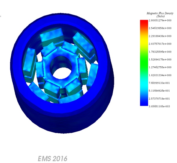
Figure 2 - 3D Model of the Magnetic Coupling Machine
The EMS Magnetostatic module is utilized to calculate flux density and analyze rotor motion. The workflow includes four essential steps: assigning the correct materials to all components, setting the required boundary conditions (known as Loads/Restraints in EMS), meshing the model comprehensively, and finally, running the analysis with the solver. This structured approach ensures precise simulation outcomes, offering detailed insights into the magnetic and dynamic characteristics of the system.
In Magnetostatic analysis with EMS, the critical material property required is the relative permeability, as detailed in the specified Table 1. This property plays a fundamental role in determining how the material will influence the magnetic field within the analysis.
Table 1 - Table of materials
| Components / Bodies | Material | Relative permeability |
| Rotor | Copper | 0.999991 |
| Outer Air | Air | 1 |
| Rotor | Mild Steel | 2000 |
| Band | Air | 1 |
| Outer thimble | Mild Steel | 2000 |
The table shows all information related to the permanent magnets used in the model.
| Components / Bodies | Material | Relative permeability | Coercivity | Remanence |
| Permanent Magnets | S2818 | 1.03884 | 819647 A/m | 1.07 T |
In EMS Magnetostatic analysis, defining the electric and magnetic conditions of a model is crucial, and this is achieved by applying specific loads and restraints to its geometric entities. These parameters are vital as they directly influence the outcome of the analysis. They are integrated as features that maintain a full association with the model's geometry, ensuring that any changes to the geometry are automatically reflected in the loads and restraints applied, thus maintaining the accuracy of the simulation's environmental conditions.
| Name | Torque Center | Components / Bodies |
| Virtual Work | At Origin | Rotor |
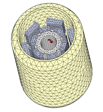
Meshing significantly impacts design analysis in EMS, which automatically calculates an optimal global element size based on the model's geometric attributes. The complexity and accuracy of the mesh, influenced by geometry, element size, and mesh controls, dictate the simulation's resolution. For preliminary analyses, larger element sizes can expedite results, whereas detailed studies require finer meshes. Motion-coupled studies benefit from a "Band" component, enabling dynamic re-meshing. Mesh Control enhances quality, allowing customization for specific solid bodies and faces, ensuring precise simulations.
| Name | Mesh size | Components /Bodies |
| Mesh control 1 | 1.66666700 mm | Permanent magnets of the rotor |
| Mesh control 2 | 2.00 mm | Inner rotor |
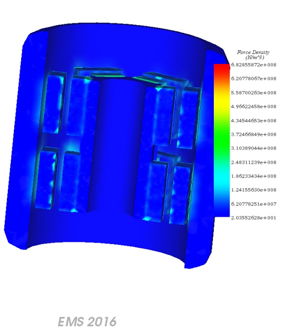
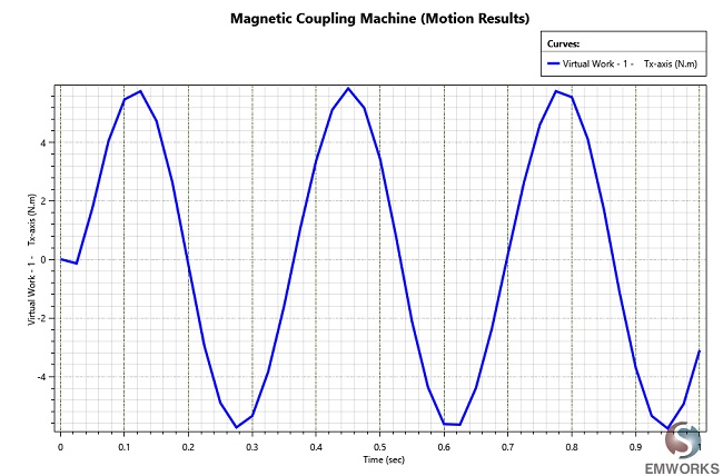
EMS facilitates dynamic analysis by enabling the visualization of flux, field, current, and more at each time step in motion studies, with options for separate viewing or animated examination of motion effects. Tabular results like force, torque, and inductance are also accessible per time step and can be graphed against variables such as time or speed. EMS supports 2D plots and motion animations, enhancing the understanding of magnetostatic effects and kinematic data, and providing a comprehensive overview of simulation outcomes including magnetic flux density, field intensity, and applied forces.
.Magnetic couplings revolutionize torque transmission with their seal-free, efficient magnetic field operation, vital for pump systems, wind turbines, and underwater vehicles. This application note delves into the virtual prototyping of a magnetic coupling machine, showcasing its design intricacies and performance through EMS Magnetostatic analysis. By simulating rotor motion and flux density, insights into torque dynamics and magnetic behavior are gained, aiding in system optimization. The structured workflow ensures accurate results, elucidating the impact of design variations on performance metrics. Meshing techniques enhance simulation resolution, while visualization tools offer comprehensive insights into magnetic flux distribution and force dynamics. This comprehensive analysis underscores the magnetic coupling machine's potential for precise torque transfer in diverse applications, emphasizing its significance in modern engineering solutions.
| Share on |