In the realm of electrical engineering, designing for electromagnetic fields presents numerous challenges, especially when utilizing specialized components like Litz wire. Litz wire, known for its unique construction aimed at mitigating skin and proximity effects, plays a crucial role in high-frequency applications. However, optimizing its design for efficiency and minimizing losses requires careful consideration of various factors. In this application note, we'll explore the key challenges associated with Litz wire design and discuss how electromagnetic simulation can be instrumental in overcoming these hurdles.
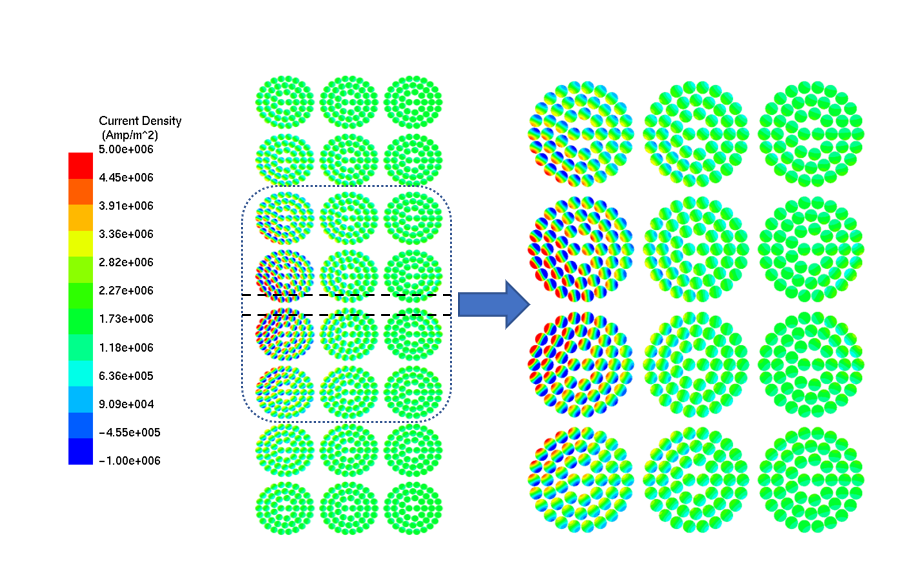
Litz wire is designed to mitigate the skin effect by dispersing current across numerous strands, yet addressing these effects grows more intricate at elevated frequencies. Electromagnetic simulation tools offer precise modeling of Litz wire behavior across frequency ranges, facilitating the identification of optimal configurations to reduce losses. Analyzing current density distribution at both low and high frequencies addresses both skin and proximity effects, serving as a crucial step in designing and optimizing Litz wire-based applications.
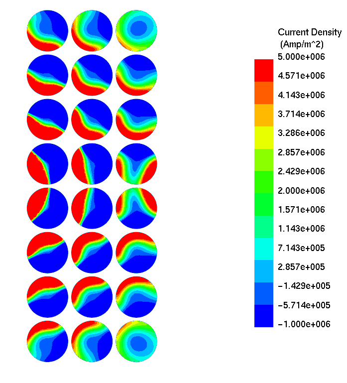
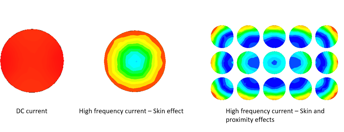 Figure 2: Current density distribution computed by EMWORKS
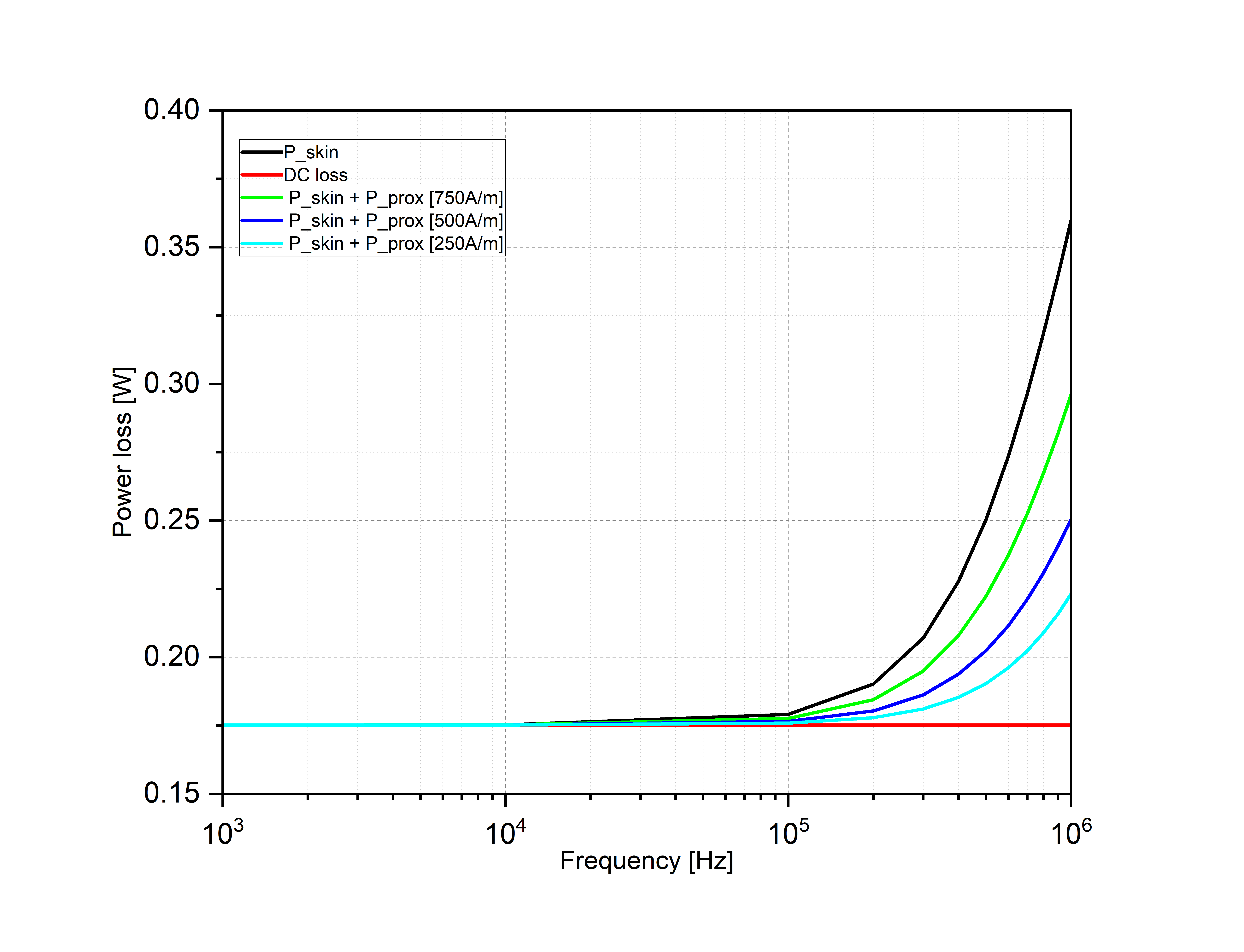
Additionally, numerical simulations allow for a detailed examination of distinct physical phenomena, such as skin and proximity losses, as shown in Figure 1-2. By analyzing these losses separately, engineers gain insights into their impact on overall performance. Illustrated in Figure 3, the computation of skin and proximity effect losses against frequency, and under different external magnetic field intensities (H), reveals a notable trend: at higher frequencies, eddy current losses escalate exponentially, surpassing DC losses significantly. Furthermore, it becomes apparent that as the external magnetic field strengthens, resulting in proximity losses, there is a notable increase in these losses. These observations underscore the critical importance of both the frequency and external magnetic field considerations in Litz wire design.
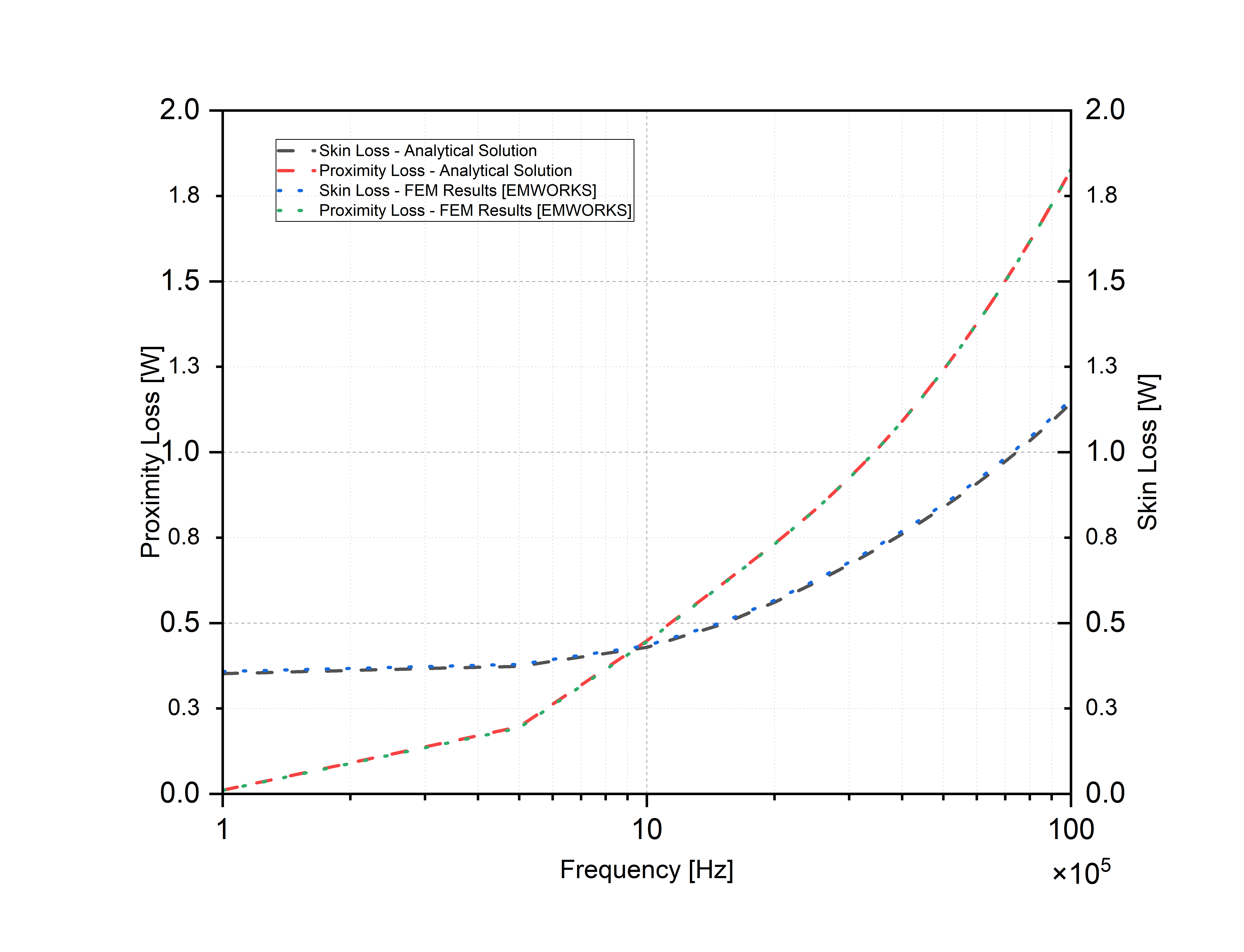
The comparison chart, shown in Figure 4, illustrates the loss results of a basic Litz wire conductor obtained through analytical calculations alongside those derived from EMWORKS FEA. Remarkably, both the skin and proximity outcomes exhibit strong agreement.
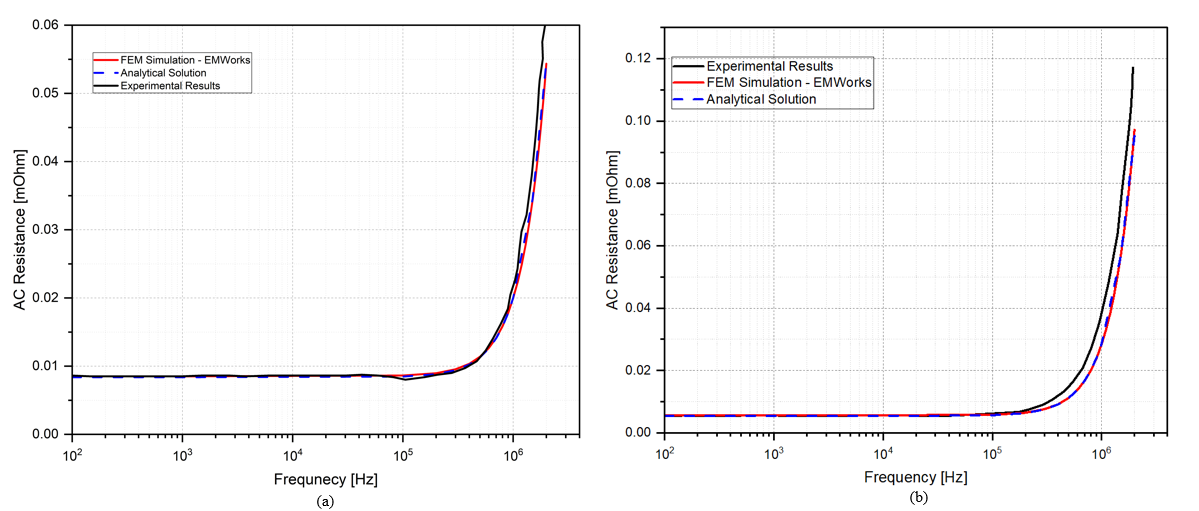
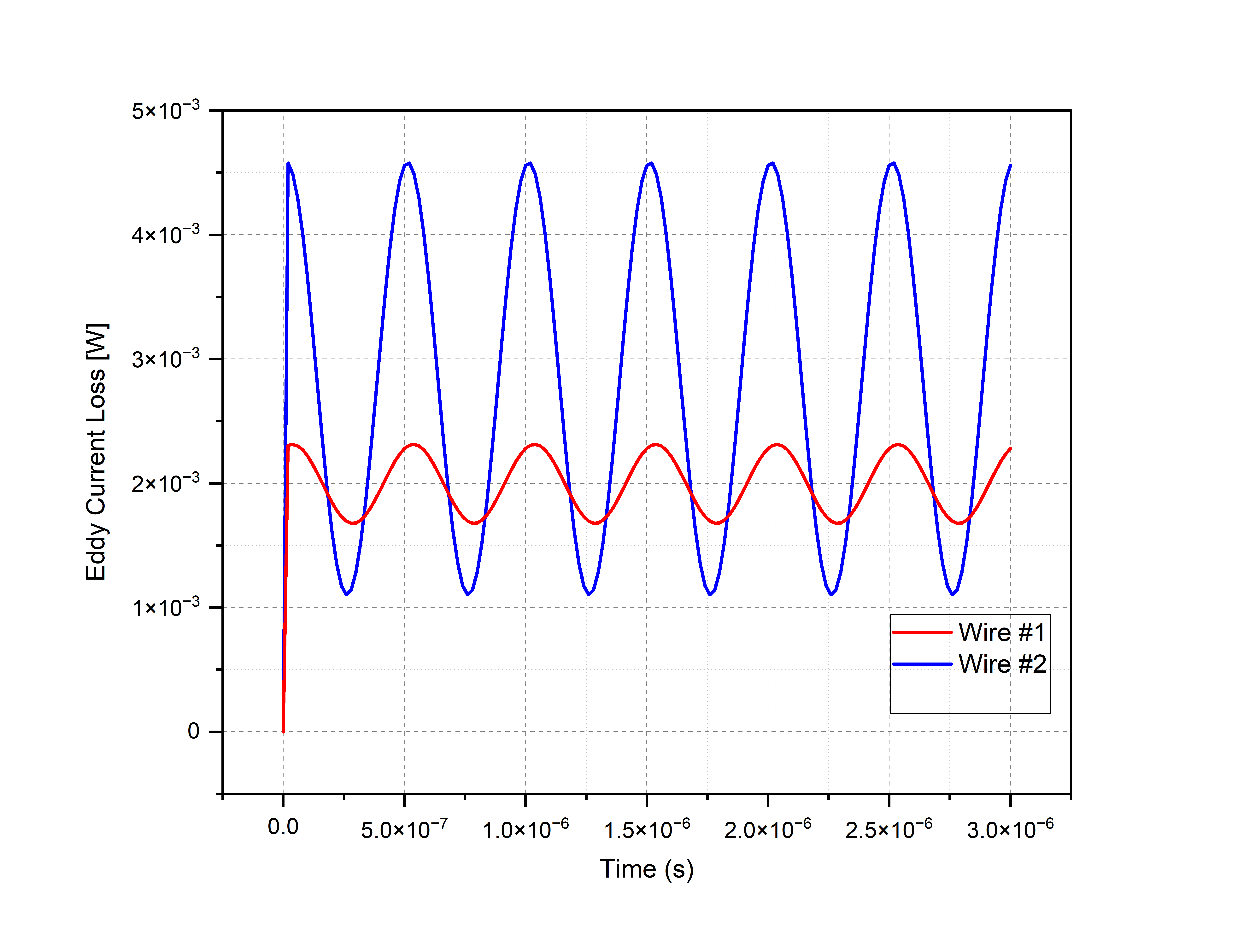
Evaluating the AC to DC resistance ratio across varying frequencies is essential in optimizing the performance of a Litz wire. Utilizing electromagnetic design software enables engineers to pinpoint the frequency range where Litz wire operates with maximum efficiency. Figure 5 illustrates the fluctuation of the AC resistance with frequency for various wire parameters. It indicates a notable increase in AC resistance beyond a certain frequency, corresponding to a skin depth significantly smaller than the radius of the strands. The findings are compared with experimental and analytical solutions, showing excellent agreement. Additionally, Figure 6 showcases the AC winding loss in the two Litz wires at a specific frequency over time. This assists designers in incorporating Litz wire into applications requiring time-domain analysis, such as electric motors and generators.
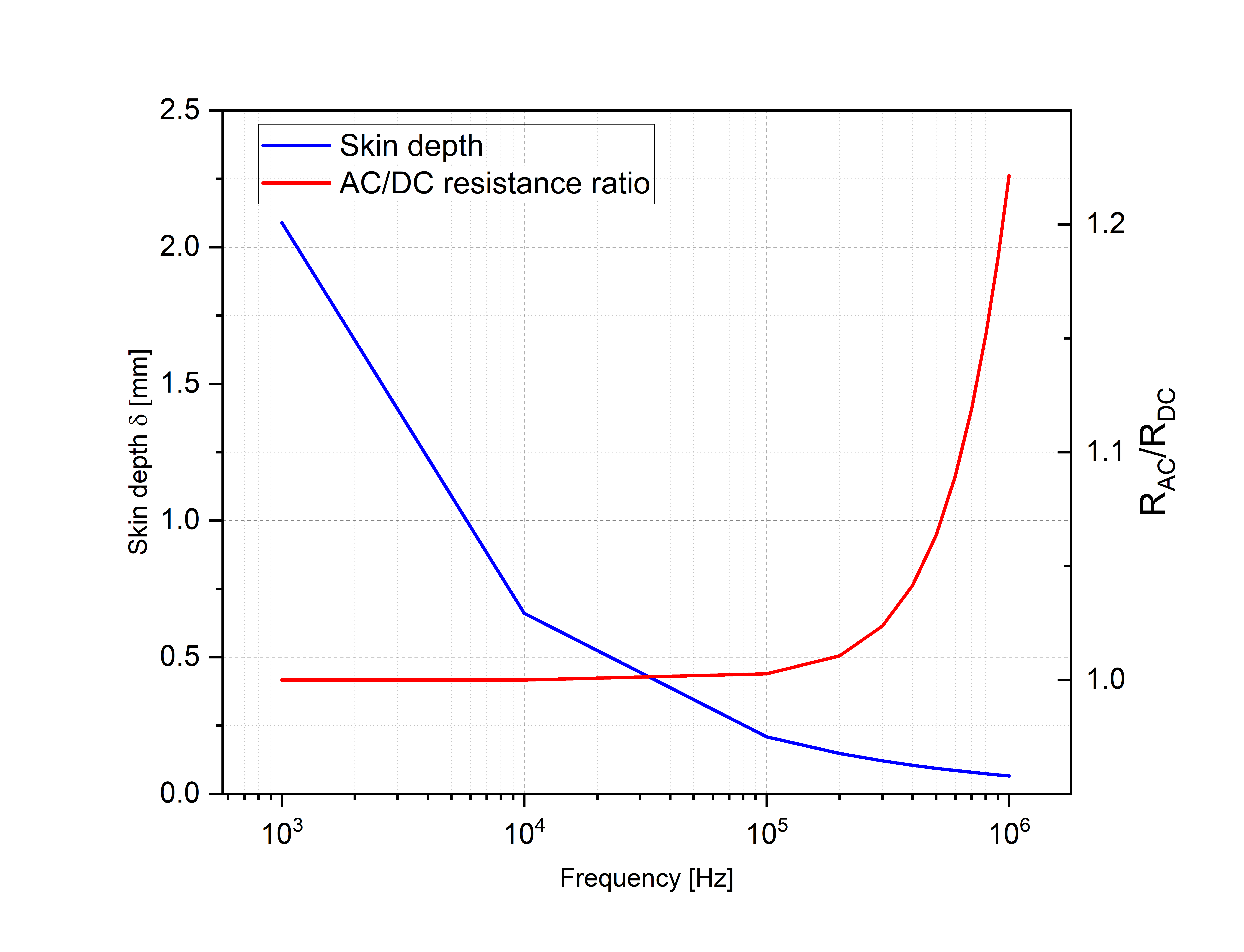
Calculating the skin depth is vital in designing Litz wire to optimize its performance and efficiency. By accurately determining the skin depth, designers can minimize AC resistance, maximize conductive area, and tailor the wire's dimensions for specific operating frequencies. This ensures efficient power transmission and mitigates issues such as temperature rise and electromagnetic interference. By addressing the skin effect, Litz wire can be optimized for various applications, enhancing overall performance and reliability. In Figure 7, the variations in the AC to DC resistance ratio and skin depth with excitation frequency are shown. Up to 100 kHz, the ratio remains nearly constant at 1, indicating equal AC and DC resistance. Within this range, the skin depth closely matches the conductor diameter, ensuring uniform current distribution. However, a noticeable change occurs around 300 kHz as the skin depth approaches the conductor radius. With higher frequencies and shallower skin depth, the resistance ratio deviates from unity due to reduced effective conductor area. To maintain a ratio close to 1, it's crucial to keep the conductor diameter approximately equal to or less than the skin depth.
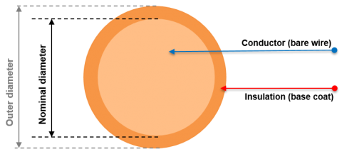
Selecting the number of strands and their diameters in Litz wire design directly influences losses. More strands decrease AC resistance but raise proximity effect losses due to increased inter-strand coupling. Conversely, larger diameters reduce resistance but raise skin losses due to decreased surface area. Electromagnetic simulation aids in optimizing these parameters by assessing their impact on losses and efficiency. Filling factor which depends on the number of strands, strand diameter and wire diameter, must be carefully evaluated versus these parameters. By simulating various configurations, designers can determine the optimal balance between AC resistance, skin and proximity losses to meet performance criteria efficiently. Figure 8 shows a close view of a single strand with insulation material and typical multi strands Litz wire arrangement.
 |
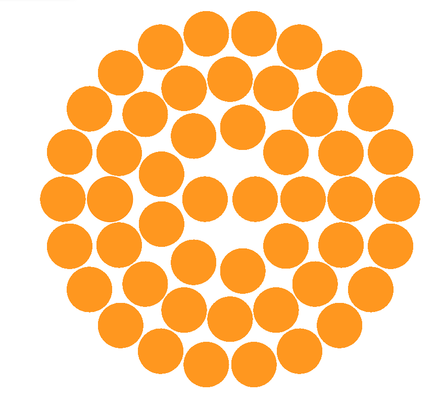 |
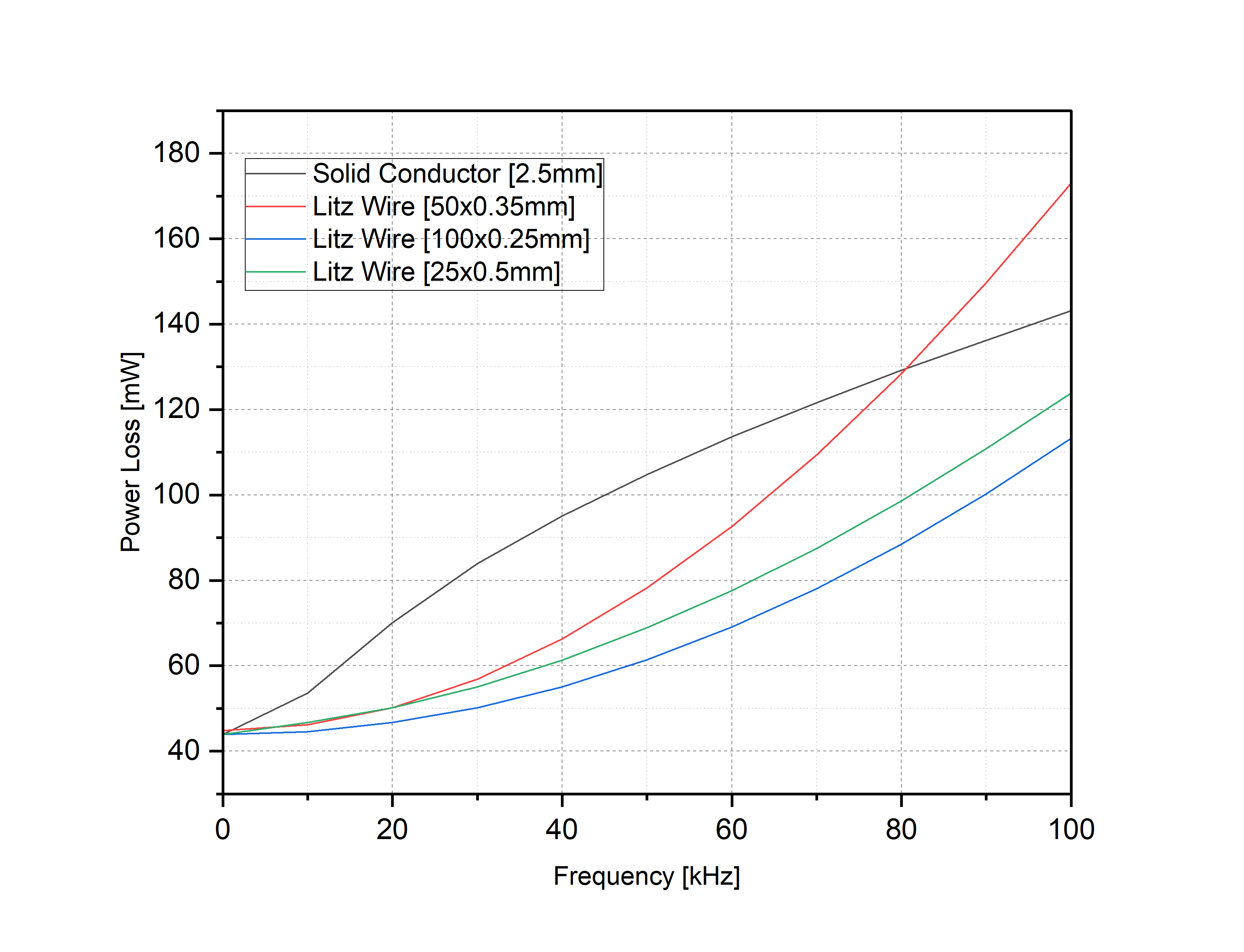
Figure 9 demonstrates the change of various Litz wire configurations versus frequency. This graph illustrates that beyond a specific frequency threshold, the Litz wire losses surpass those of solid wires due to the prevalence of internal proximity-effect Electromagnetic simulations play a crucial role in identifying the frequency ranges where the internal proximity effect becomes significant and evaluating its impact on wire performance. By understanding these effects, designers can make informed decisions about the use of Litz wire and implement mitigation strategies, such as optimizing strand arrangements or considering alternative conductor configurations, to minimize losses and ensure optimal performance across the entire frequency spectrum.
Choosing between Litz wire and solid conductors depends on factors like frequency of operation, power losses, space constraints, and cost considerations. Litz wire is advantageous at higher frequencies due to reduced eddy current effect losses, making it suitable for applications where frequency response and efficiency are critical. Electromagnetic simulations help compare the losses and frequency responses of Litz wire and solid conductors under various conditions, aiding in informed decision-making. While Litz wire excels in minimizing losses at higher frequencies, solid conductors may be more cost-effective and simpler to manufacture, particularly for low-frequency applications. Electromagnetic design enables designers to optimize conductor choice based on performance requirements and constraints, ultimately improving the efficiency and effectiveness of the system. From Figure 10, it can be seen that beyond certain frequency, the Litz wire experiences more losses compared to a solid conductor. This is because the Litz wire lost its efficiency as the skin depth becomes smaller than the strands diameter and the increased internal and external proximity effects.
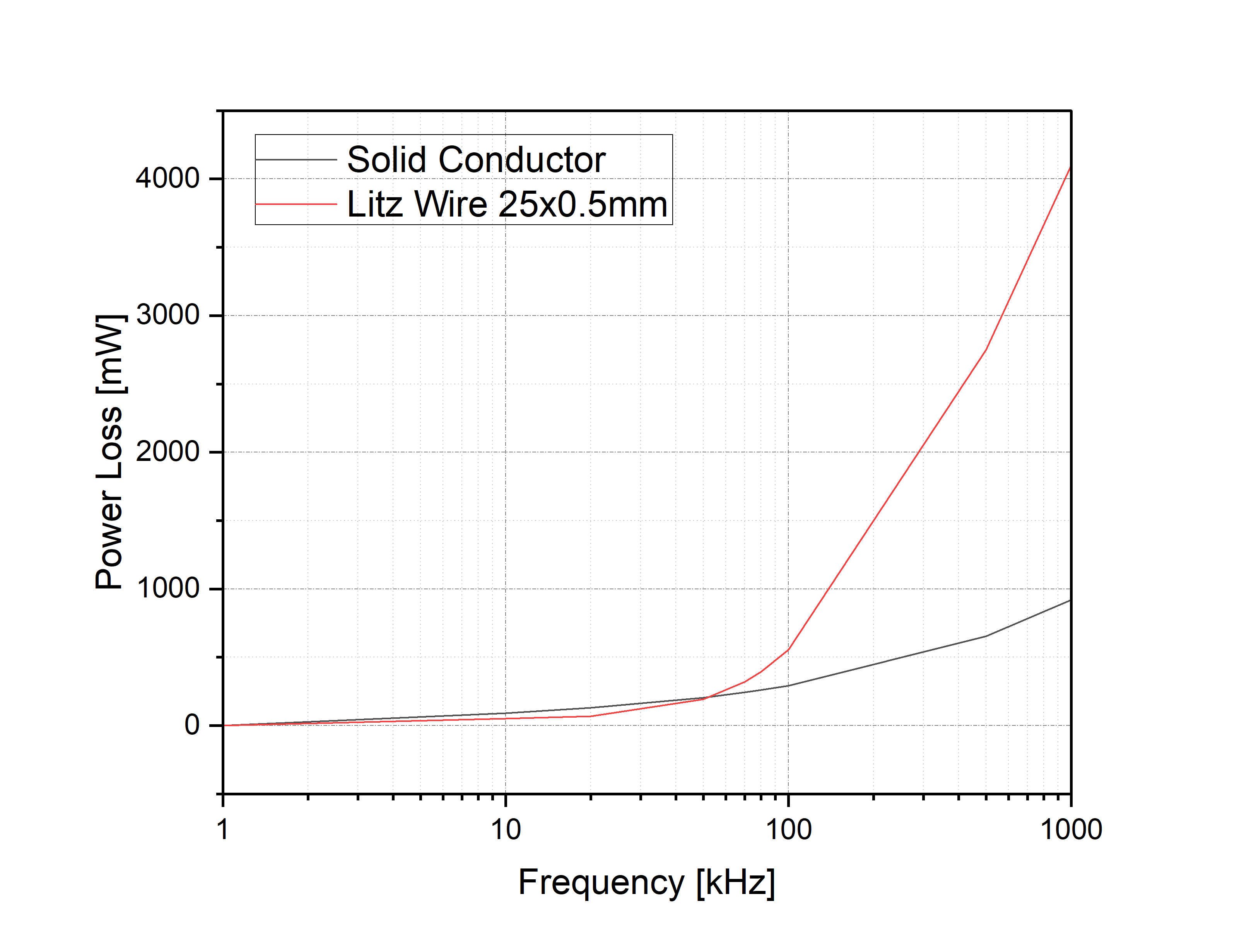
Figure 11 demonstrates a comparison between a coil made of a solid conductors (Figure 11a) and a coil made of Litz wire (Figure 11b). It is obvious that the Litz wire coil shows more uniform current distribution compared to the solid conductor coil. This is attributed to the reduce skin and proximity effects offered by the Litz wire.
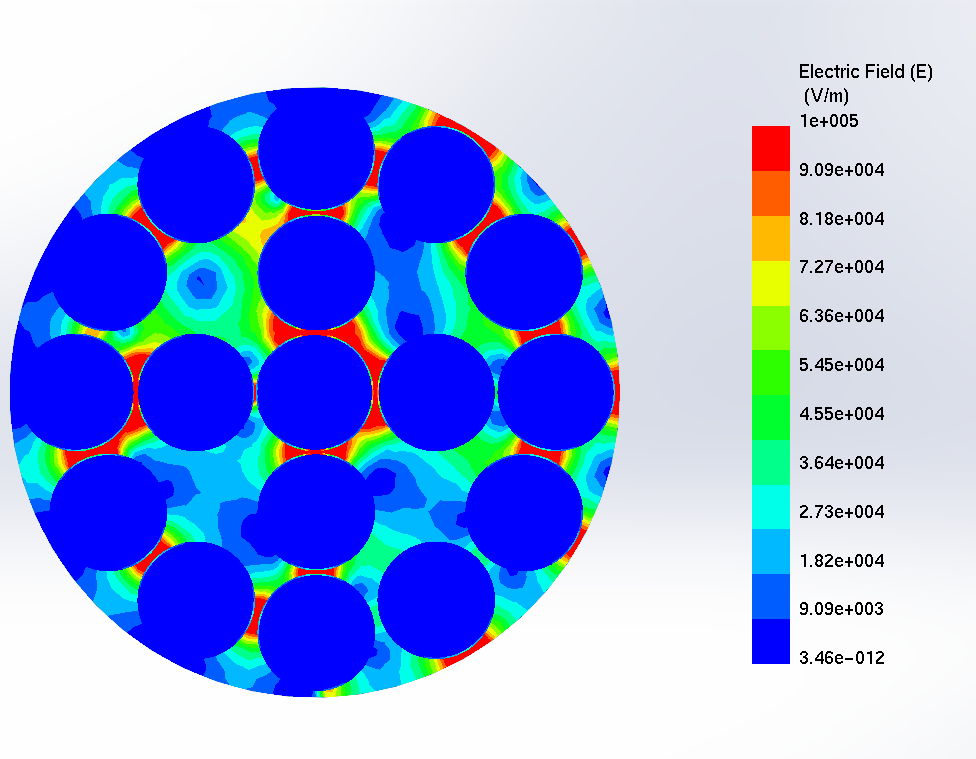
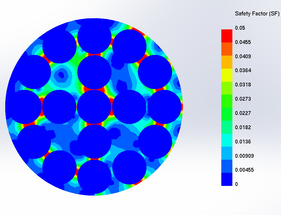
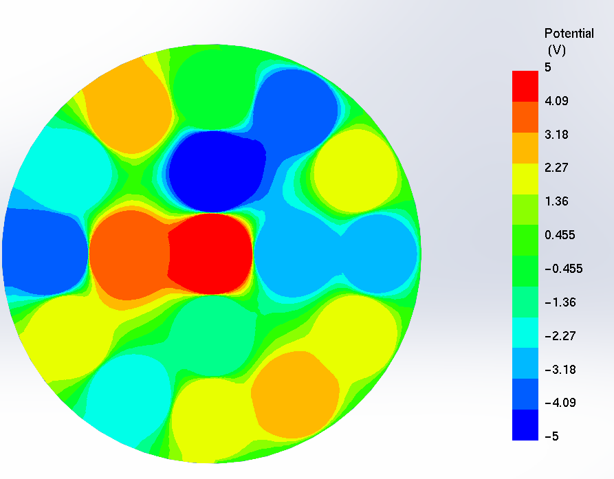
Electromagnetic design plays a crucial role in assessing insulation dielectric strength for Litz wire. By using electromagnetic design software, engineers can simulate voltage stress, temperature effects, and environmental conditions to ensure that the insulation can withstand the required voltage levels without breakdown. This process helps enhance reliability and safety while optimizing Litz wire performance, as shown in Figure 12.
 (a) |
 (b) |
 (c) |
|
The exploration of Litz wire design within this application note highlights the indispensable role of electromagnetic simulation, particularly through EMWORKS, in addressing the unique challenges presented by high-frequency applications. By meticulously analyzing skin and proximity effects, EMWORKS enables engineers to optimize Litz wire configurations, striking a balance between efficiency and performance. The detailed simulations and comparative analyses presented not only illuminate the path to enhanced electrical component design but also reinforce the necessity of tailored engineering solutions.
| Share on |