The rollout of 5G wireless communication, driven by the need to support increasing smart device usage and live streaming, leverages 5G millimeter-wave (mmWave) antennas to boost bandwidth and data traffic capacity. These advancements face challenges like significant path loss from atmospheric absorption, which high-gain antennas can mitigate. Electromagnetic (EM) simulation is crucial for optimizing these antenna designs, ensuring reliable high-speed communication in various environmental conditions, making it essential for successful 5G deployment.
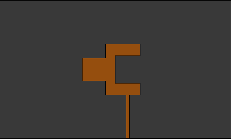
A single-element antenna, which is used in constructing the 5G mmWave antenna array, is shown in Fig.1. The antenna is constructed on a Rogers 5880 dielectric substrate. The microstrip feedline is connected at the U-edge of the antenna.

The above antenna is simulated, and the following results are obtained:
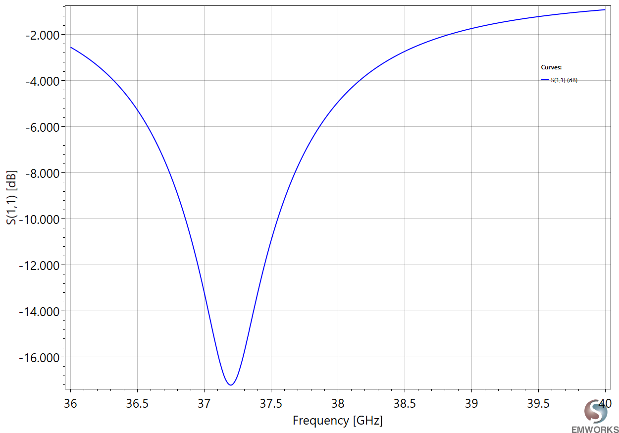
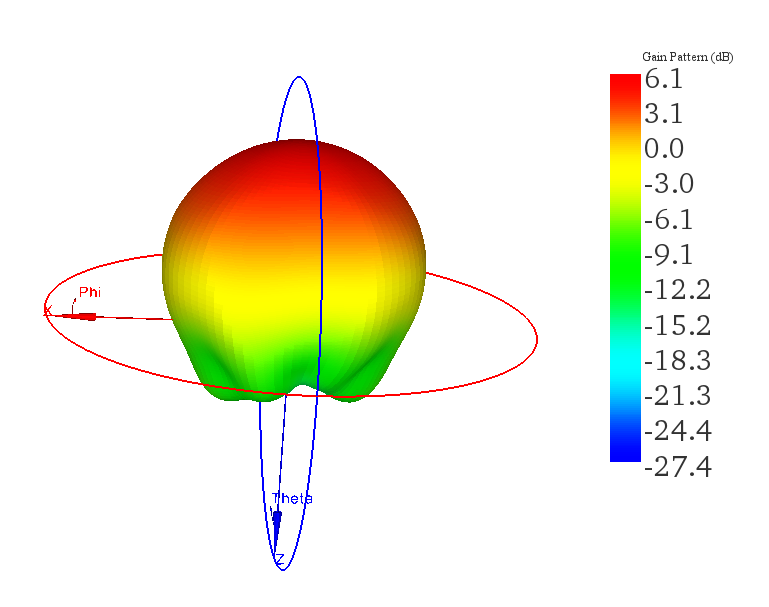
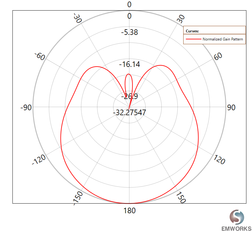
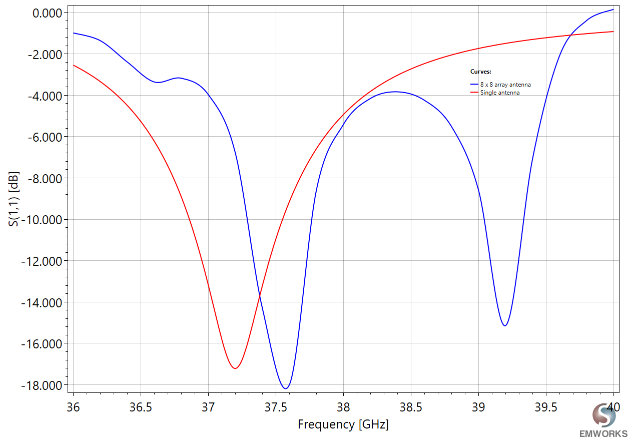
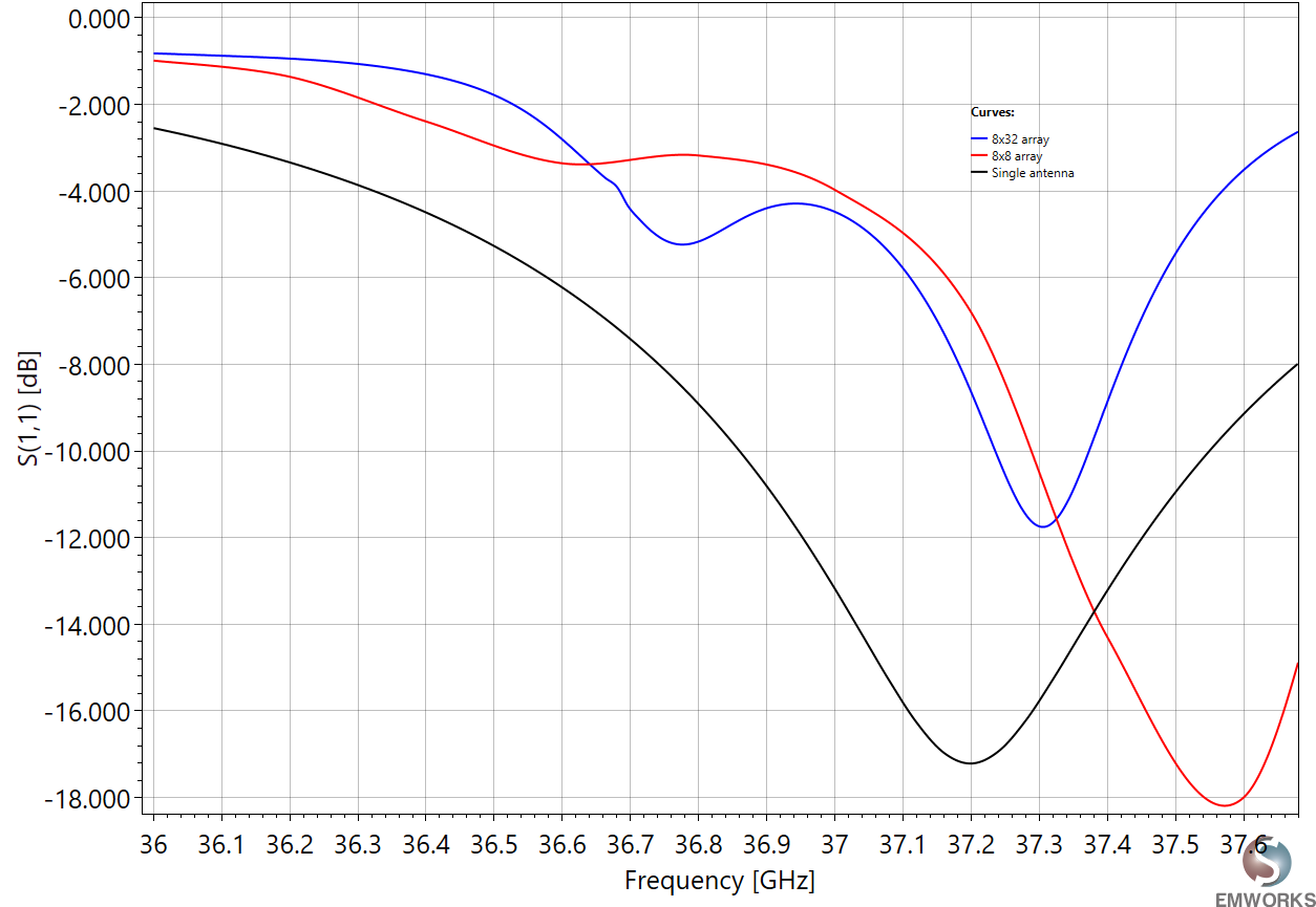
The data, shown in Fig. 4-5, indicates that the antenna operates with a resonance frequency of 37.2 GHz, exhibiting a reflection coefficient of -17 dB, which suggests good impedance matching at this frequency. The antenna's maximum gain of 6.1 dB, while adequate for mobile handset applications, highlights a limitation when considering the stringent requirements of 5G mmWave base stations. The higher gain requirements for base stations stem from the need to counteract the significant challenges posed by signal attenuation, including path loss, multipath effects, and atmospheric absorption, inherent in the 5G mmWave spectrum. These factors collectively demand antennas with higher gain to ensure reliable communication over longer distances and through various environmental conditions. Therefore, while the antenna's performance may be satisfactory for individual user equipment, the quest for enhancing 5G mmWave base station capability necessitates further innovation in antenna design to achieve higher gains and more effective signal propagation.
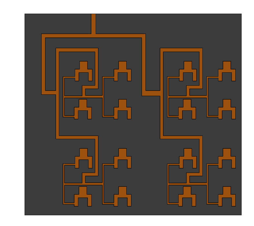
The geometry of the 8x8 antenna array is shown in Fig. 6. The proposed antenna consists of 16 interconnected antennas using power dividers. The array is excited through a 50-? feed network. The spacing between the elements is optimized to obtain good performance.
Simulating the 8x8 antenna array gives the following results.
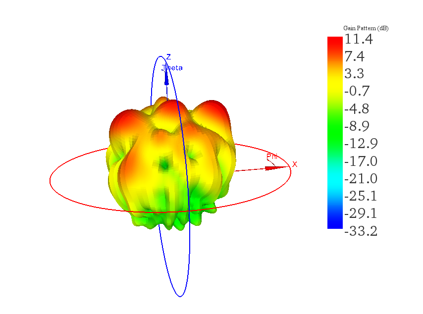
The gain plot, shown in Fig. 8, highlights a crucial aspect of antenna array design: by integrating multiple antenna elements into an array, significant improvements in gain can be achieved compared to using a single-element antenna. This phenomenon is attributed to the constructive interference of signals from the array elements, which, when precisely phased and aligned, amplifies the signal strength in the desired direction. The nearly doubled gain of the array underscores the efficiency of using antenna arrays to enhance signal transmission capabilities, making them highly effective for applications requiring improved signal reach and quality. Such an increase in gain not only improves the directivity of the antenna system but also its overall performance in transmitting and receiving signals, making antenna arrays a key technology in advancing wireless communication systems.
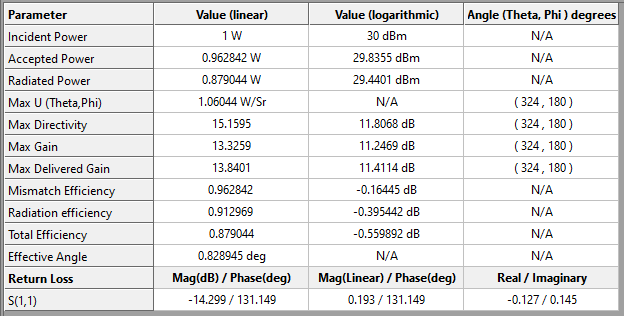
In HFWorks, the "Far Field Results Table" serves as a comprehensive summary of key antenna parameters critical for understanding and optimizing antenna performance. This table includes vital metrics like directivity, which measures the antenna's ability to focus energy in a particular direction; gain, which quantifies the power transmitted in the direction of peak radiation compared to that of an isotropic source; radiation efficiency, indicating the percentage of input power that is effectively radiated; and total efficiency, which takes into account both radiation efficiency and losses within the antenna system. These parameters are essential for antenna designers to assess and refine their designs, ensuring optimal performance for specific applications, particularly in contexts requiring precise directional transmission and high efficiency.
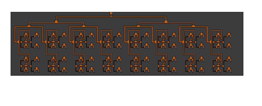
The antenna array is composed of 64 interconnected antennas using power dividers. The array is excited through a 50-? feed network. It has an overall dimension of 30 × 110 mm².
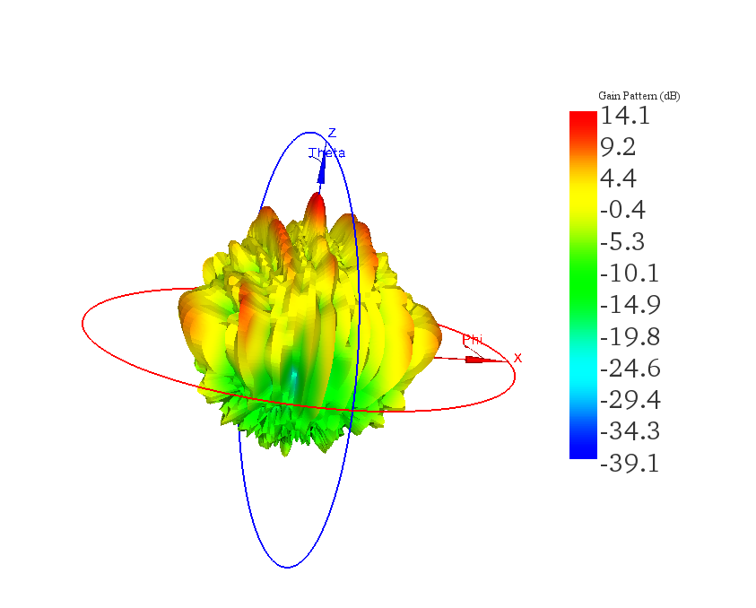
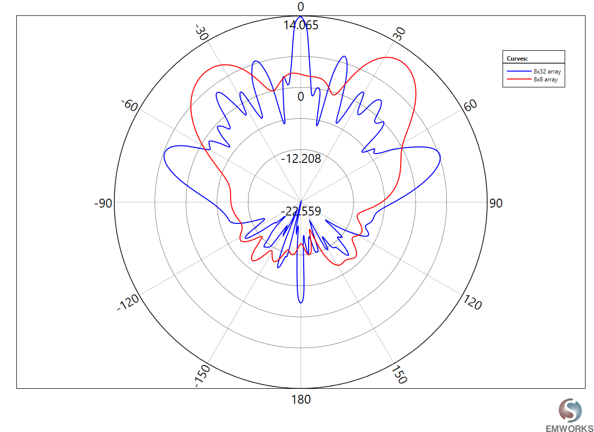
The observation from the graph, shown in Fig. 12-13, indicating that the 8x32 antenna array achieves a high gain of 14 dB is significant for 5G mmWave base station applications. This level of gain is particularly valuable in the context of 5G mmWave technology, where overcoming the challenges of signal attenuation, path loss, and atmospheric absorption is critical for maintaining robust and reliable wireless communication. The enhanced gain offered by the 8x32 array configuration can effectively extend the reach of base stations, improve signal quality, and ensure stable connections over the wide bandwidths utilized in 5G networks. This makes such antenna arrays integral to deploying efficient and high-performance 5G mmWave base stations, enabling them to support the high data rate demands and connectivity requirements of modern wireless communication systems.
In this application note, we have delved into the pivotal role of high-gain antenna arrays in enhancing the deployment of 5G mmWave technology, highlighting their capacity to meet the rigorous requirements for bandwidth expansion and reliable, high-speed communication. Through the simulations conducted in HFWorks, including analyses of single-element antennas and more sophisticated 8x8 and 8x32 antenna arrays, we've showcased the significant gains in signal transmission capabilities necessary for the success of 5G mmWave base stations. These simulations underscore the vital importance of electromagnetic (EM) simulation tools like HFWorks in refining antenna design to mitigate issues such as path loss, multipath effects, and atmospheric absorption. The progression in antenna array technology, evidenced by marked gain improvements in larger arrays, suggests a robust approach to overcoming the inherent challenges in 5G mmWave communication.
Design of high gain base station antenna array for mmwave cellular communication systems
D.A. Sehrai1, J. Khan, M. Abdullah, M. Asif, M. Alibakhshikenari, B. Virdee, W.A. Shah7, S. Khan, M. Ibrar, S. Jan, A. Ullah & F. Falcone
| Share on |