Rectangular half-height WR2300 waveguides are essential for directing power to accelerator cavities, particularly focusing on the transition section influenced by the iris's varying coupling needs. This study, leveraging HFWorks, showcases the design and simulation of RF couplers and includes an RF-to-thermal analysis to evaluate critical parameters like return and insertion losses, resonant frequency, and thermal efficiency.
The coupler structure, detailed in Figure 1, consists of three key components: an incoming WR2300 half-height rectangular waveguide (part I), a central ridge waveguide (part II), and an end ridge (part III), as shown in Figure 2. The dimensions of this ridge waveguide coupler are 400mm x 400mm x 150mm.
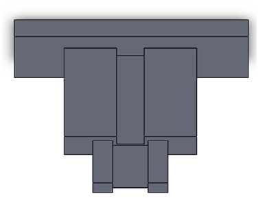
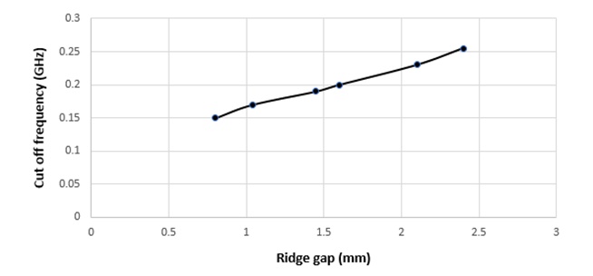
Figure 2 presents a side view schematic of the waveguide coupler. We utilized ATLASS to simulate how the cut-off frequency varies with the ridge gap for the TE10 mode. The outcomes of this study are graphically illustrated in Figure 3.
.jpg)
The geometrical parameters can be specified within a file and seamlessly imported into CAD by leveraging the software's Equations feature. A concise summary of these parameters is presented in Table 1.
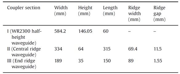
Figure 3 illustrates the fluctuation in the cut-off frequency for the TE10 mode, achieved by altering the ridge gap through ATLASS simulation.
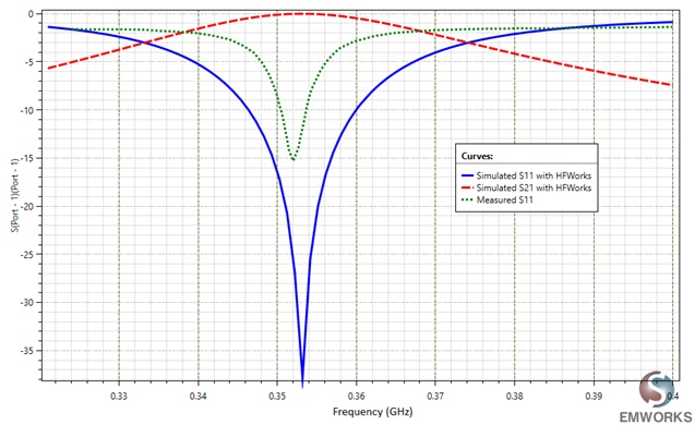
The simulated results for return loss (S11) and insertion loss (S21), conducted through HFWorks, are juxtaposed with the measured outcomes of the coupler in Figure 4. Additionally, Figure 4 reveals that the waveguide coupler exhibits resonance at 0.353 GHz.
HFWorks carries out an automatic calculation of the conductor loss, representing the thermal load imposed on the coupler walls. This information is then integrated into the thermal module, considering an incident power of 250 kW. The analysis takes into account the surrounding air with an assumed convective heat transfer coefficient (h) of 1000 W/m²·K and an ambient temperature of 293 K.
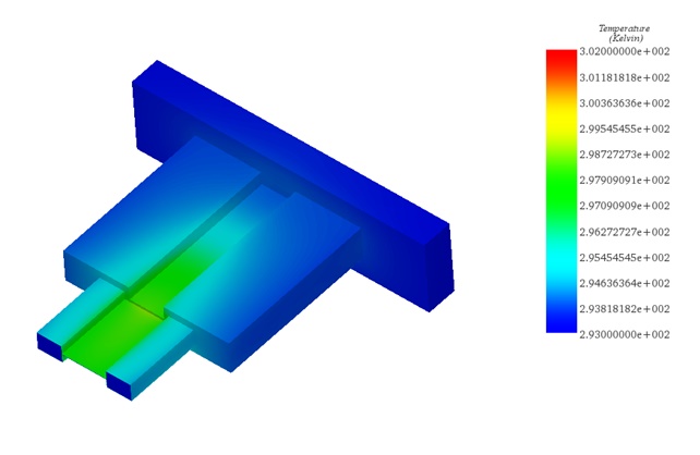
Figure 5 illustrates the temperature distribution, and it is evident that there is minimal temperature rise despite the application of a 250 kW incident power. This observation affirms the absence of any thermal-structural issues with the waveguide.
This application note focuses on the utilization of HFWorks for the design and simulation of RF couplers, particularly targeting rectangular half-height WR2300 waveguides essential in power delivery to accelerator cavities. It highlights the coupler's structure, which includes an incoming waveguide, a central ridge, and an end ridge, measuring 400mm x 400mm x 150mm. The study uses ATLASS to explore how the TE10 mode's cut-off frequency varies with changes in the ridge gap. Results, as shown in Figure 3, detail this frequency fluctuation, while Figure 4 contrasts simulated return and insertion losses with actual measurements, revealing a resonance at 0.353 GHz. Additionally, HFWorks automatically computes the conductor loss, crucial for assessing the thermal impact on the coupler walls under a 250 kW power load. The temperature distribution, illustrated in Figure 5, confirms minimal temperature increase, suggesting no thermal-structural issues.
[1] https://www.emworks.com/product/ATLASS
[2] Rajesh Kumar, Mentes Jose, G.N. Singh, Girish Kumar and P.V. Bhagwat "RF characterization and testing of ridge waveguide transitions for RF power couplers ", published at Nuclear Instruments and Methods in Physics Research A 838, pp. 66-7, 2016
| Share on |