In this example, we introduce a validated 5-pole H-plane Iris Filter (WR75). We conducted a comprehensive comparison between the simulation results obtained with HFWorks and the measurements outlined in [1]. This bandpass filter consists of five irises, each with a thickness of 0.05 inches. The figure below illustrates the dimensions of the cavities and iris windows. The filter has been successfully integrated into a WR75 waveguide, demonstrating excellent performance across the 11.5 to 12.5 GHz frequency range, which is crucial for satellite communications.
.jpg)
Figure 1 - the structure's 3D view in SolidWorks
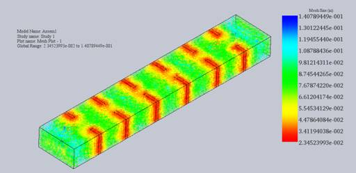
Figure 2 - Mesh of the structure
To calibrate the ports and specify the electric field orientation, integration lines can be utilized. In this setup, the Irises are treated as Perfect Electric Conductors (PECs). Given the critical dimensions of the Irises, it's advisable to employ a fine mesh for accurate simulation results.
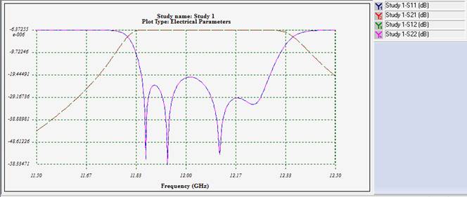
To assess the simulation's accuracy, we examine the return loss and insertion loss curves. These curves demonstrate that the simulator accurately captures the stopband characteristics. As mentioned earlier, we employed a fast sweep plan for this example, but it's worth noting that the discrete sweep provides even more precise results, albeit with a longer simulation time. The following figures illustrate both the simulated and measured curves for comparison:
.png)
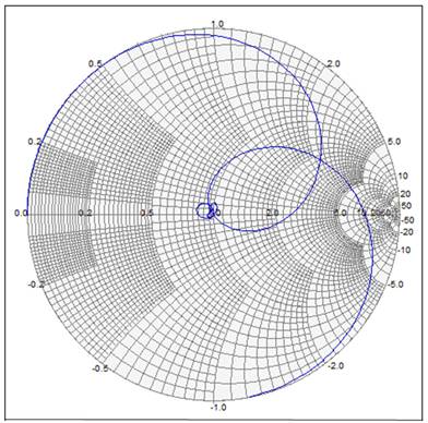
Figure 3 - Insertion and return losses (2D and Smith Chart)
When visualizing Scattering Parameters, we utilize the Electrical Parameters results folder and have the option to select either a 2D or Smith Chart plot. These plots can be further examined using markers, and it's possible to plot predefined curves like circles with constant VSWR on the Smith Chart. The figure below displays both the return loss and insertion loss of the filter for reference.
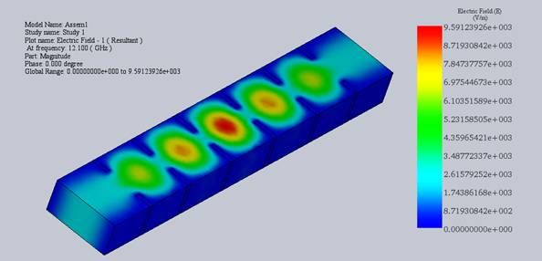
Figure 4 - Electric field distribution
The electric field distribution is depicted in the figure below. When animated, it provides a clear visualization of electromagnetic waves propagating through the circuit and reaching the second port.
In this application note, we introduced a validated 5-pole H-plane Iris Filter (WR75), showcasing its excellent performance across the 11.5 to 12.5 GHz frequency range critical for satellite communications. Through a comprehensive comparison between HFWorks simulation and the measurements outlined in [1], we verified the accuracy of our results. The filter, composed of five irises, demonstrated remarkable integration into a WR75 waveguide. HFWorks' Scattering Parameters solver provided comprehensive analysis, focusing on return and insertion losses. Calibrating ports and specifying electric field orientation ensured accurate simulation results, aided by fine meshing for critical dimensions. Examination of return and insertion loss curves confirmed the simulator's precision in capturing stopband characteristics. Visualization of Scattering Parameters, along with electric field distribution, provided valuable insights. Overall, our study highlights the efficacy of HFWorks simulation in designing and optimizing H-plane iris filters for microwave applications.
[1] Power-Handling Capability for RF Filters Ming Yu IEEE Microwave Magazine -October 2007 [link]
| Share on |